DR Power Towable Backhoe User Manual
Page 17
CONTACT US AT www.DRpower.com 17
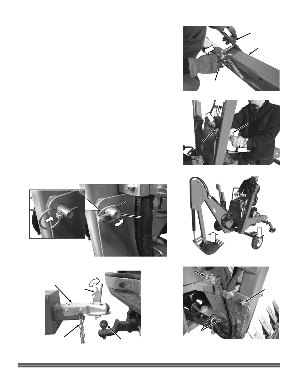
Hitch
Pin
Figure 24
Hitch
Pin
Hitch Pin
Storage
Figure 21
Front
Stabilizer
Lynch
Pin
Hitch
Pin
3.
Pull the Front Stabilizer Lynch-Pins from the Hitch pins and remove the
Hitch Pins (Figure 21).
4.
Raise the Front Stabilizers to the Vertical position (Figure 22).
5.
Line up the holes in the Front Stabilizers and insert the Hitch Pins. Secure
the Hitch Pins with the Lynch Pins.
6.
Start the Backhoe Engine and raise the Boom to lower the Backhoe onto the
Wheels (Figure 23).
7.
Use the Controls to center and pull in the Boom, pull the Crowd arm all the
way towards you, and pull the Bucket in. This will line up the holes for the
next step.
NOTE: You may need to check that the holes are aligned properly before you shut
down the Engine.
8.
Move the Throttle Control Lever to the idle position and turn the Engine
Ignition Switch to “OFF”.
9.
Remove the Lynch Pins from the Hitch Pins and then remove the two Hitch
Pins from the storage area. Install the Hitch Pins into their positions (Figure
24).
10.
Insert the Lynch Pins into the Hitch Pins and secure them by snapping the
Lynch Pin Ring over the Hitch Pin (Figure 25).
11.
Rotate the Latch Assembly up and lift the Hitch Coupler of the Backhoe onto
the tow vehicle’s Tow Ball (must be a 2" tow ball) (Figure 26).
Figure 22
Front
Stabilizer
Lynch
Pin
Hitch
Pin
Figure 23
Figure 25
Linchpin
Hitch
Pin
Boom
Assembly
Figure 26
Tow
Hitch
Assembly
2" Tow Ball
Latch
Assembly
Locking
Trigger
Safety Chains