ESI Waveterminal 2496 User Manual
Page 12
13
3. SYNC IN/SYNC OUT
These pins are used for synchronizing the WT 2496 with other ESI products.
4. S/B IN
Connect a digital audio output header pin on the SoundBlaster Live Value soundcard to S/B
IN to get the SoundBlaster’s digital audio output directly into the WT2496. Choose SB
LINK IN as the Digital In selection in the WT2496 Control Panel to receive and monitor the
SoundBlaster digital output signal on the WT2496.
5. S/B OUT
Connect the digital audio input on the SoundBlaster Live Value soundcard to S/B OUT to
send the WT2496’s digital output to the SoundBlaster directly. In the WT2496 Control Panel
SB-LINK OUT, you can decide what you send to the SoundBlaster’s digital audio input – CD-
ROM digital audio, coaxial digital audio input source, or the digital audio mix output of the
WT2496
.
The SB Link feature was specifically designed for SoundBlaster Live Value users who
can not use the digital bracket option. The Provided pin map on the SB card is only for
the SB Live Value Cards.
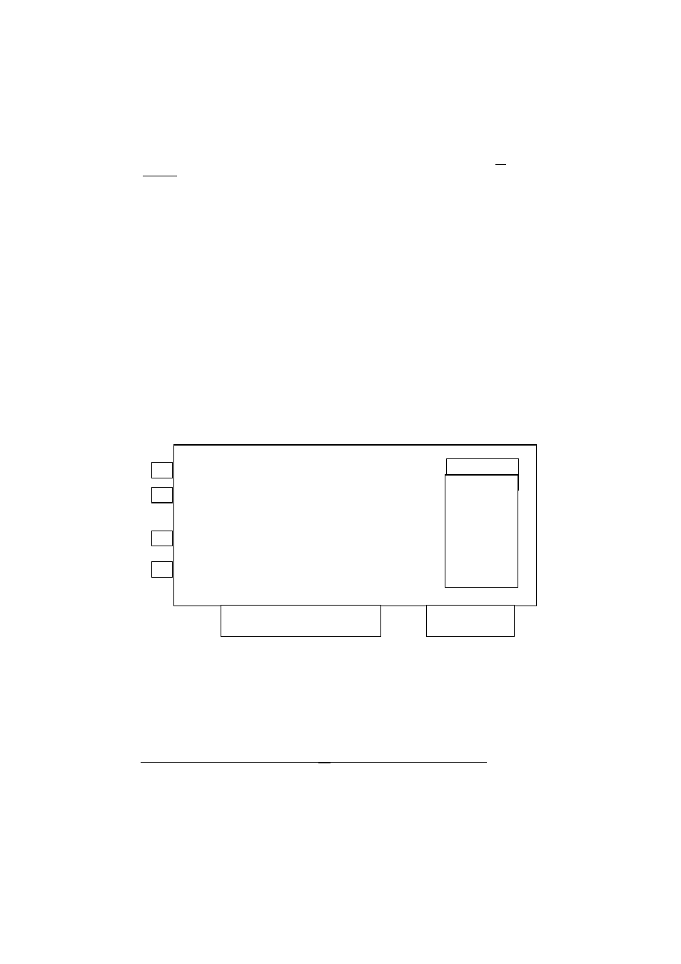
Directions for connecting the SoundBlaster Live Value to the Waveterminal 2496
12-pin Header Block on the Right Edge of SB Live Value
J 10
1 2
3 4
5 6
7 8
9
10
11
12