Fenix ECOFLEX TAC User Manual
Page 4
4
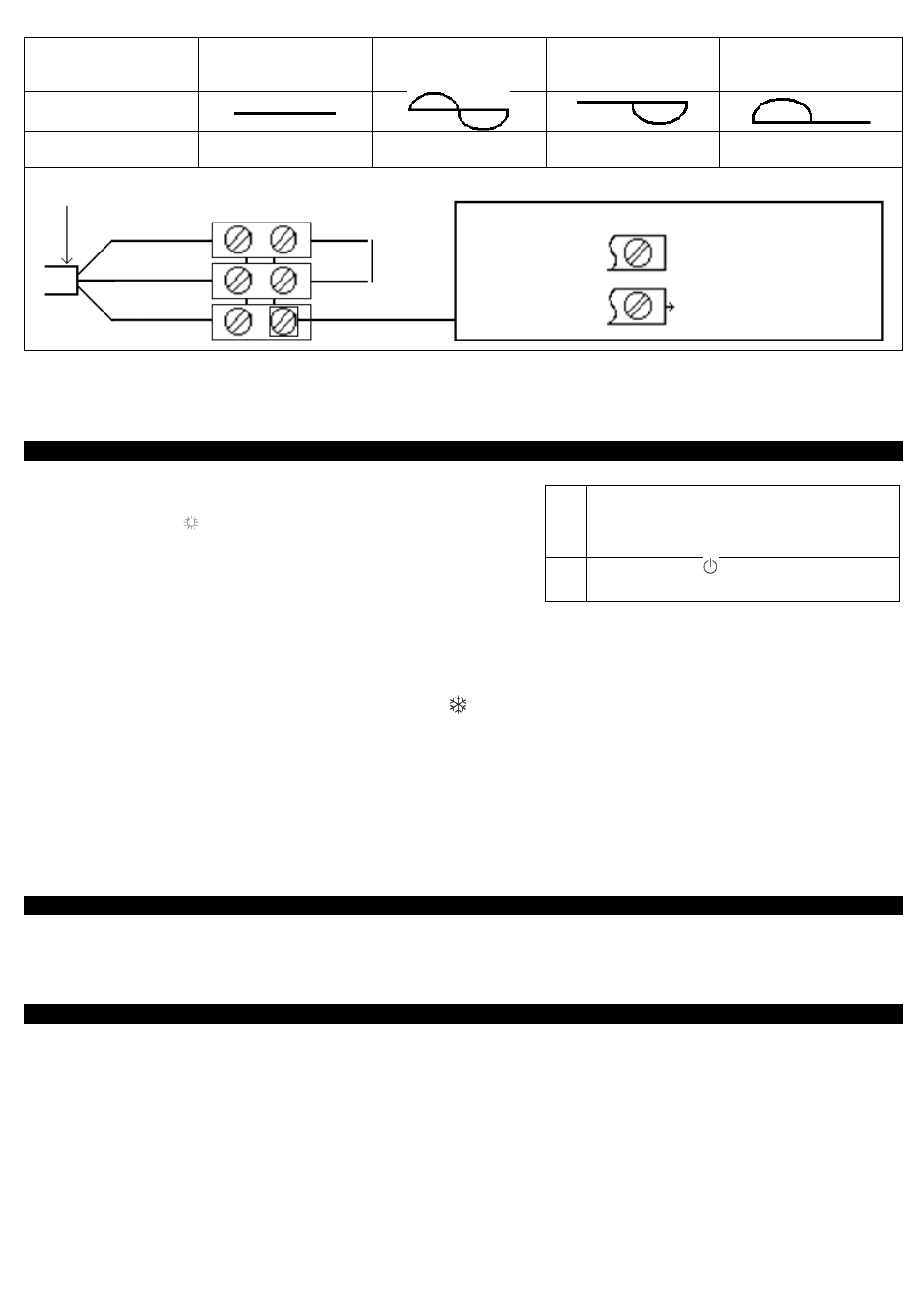
Commands
Received
Absence de signal
Complete
altermation
230 V
Negative
Half/altermation
– 115V
Positive
Half/altermation
+ 115V
Oscilloscope
Ref/Neutral
Mode
obtained
CONFORT
ECO
ANTI - FREEZE
STOP HEATING
LOAD SHEDDING
1.3.3 Wall mounted installation (Figure
❼)
- Place the device inclined on the brackets C and rotates the device to place it on the brackets D. Lowering the device on the
bracket. A click indicates that the device is attached and locked. To unlock the attachment tab, grab a screwdriver and
push the tab (at the top left of the attachment tab behind the device) towards the wall. Lift the device while holding the tab
with the screwdriver. Tilt it forward and remove it from the supports C.
2. Utilisation
2.1 How to fix the comfort mode? (Figure
❽)
- The Comfort mode allows setting the desired temperature using the
control knob.
- Put the switch H on
, and then set the control knob I on the desired
position, the heating indicator G lights if the ambient temperature is
lower than desired one. Wait until the temperature stabilizes.
2.1.1 How to fix the Eco mode?
- ECO mode allows lowering the temperature of Comfort mode from 3 to
4°C during unoccupied periods of the room. It is recommended that this mode should be used if the room is unoccupied for
more than 2 hours. Put the switch H on ECO and then set the control knob I to the desired position, the heating indicator G
lights if the ambient temperature is lower than desired ECO temperature. Wait until the temperature stabilizes.
2.1.2 How to fix the Frost Free mode?
-
It is the position of the switch that keeps the temperature at approximately 7 ° C in the room during prolonged absence from
the house (usually more than 24 hours). Put the switch H on
.
2.1.3 How to program your device in Comfort, ECO or Frost Free mode?
- Devices equipped with an electronic thermostat are able to receive orders. There are two solutions:
- By pilot wire (black wire) for devices without plug thanks to the system Chronopass or a wall pilot wire box
- By carrier current with an interface on each device in addition to a Chronopass system or a wall carrier current box.
2.1.4 How to lock the commands (Figure
❾)?
It is possible to lock or limit the use of the control knob I and to lock the switch H to prevent manipulation. Lift the unit from
the wall bracket. On the back of the thermostat, remove the pins J from their support:
- The K position allows locking the control knob.
- The L position allows limiting the utilisation of the control knob.
- The M position allows locking the H switch on the desired mode.
3. Recommendations for use
- There is no point in setting maximum heating; the room temperature will not rise any quicker. If you leave for several hours,
remember to reduce the temperature.
- If you have several units in a room, let them operate simultaneously. This will give you a more uniform temperature without
increasing electricity consumption. This also applies for an unoccupied room; it is more interesting to let the device operate
on a lower setting than turn it off completely.
4. Maintenance
- To maintain performances of your unit, you should clean the upper and lower grids of the unit about twice a year using a
vacuum cleaner or a brush.
- Have a professional check the inside of the unit every five years. Dirt may collect on the grids of the unit if the atmosphere
is polluted. This phenomenon is due to the poor quality of the ambient air. In this case, it is recommended to check that the
room is well ventilated (ventilation, air inlet, etc.), and that the air is clean. The unit will not be replaced under the guarantee
because of this type of dirt. The unit casing should be cleaned with a damp cloth, never use abrasive products.
G
Indicator for heating. It indicates the
periods in which the resistance is working.
With a stabilized temperature, it flashes
and if the temperature is too high, it stops.
H
Slider or switch
I
Control knob of the temperature
Neutral = Blue
Phase = Brown
Pilot Wire = Black
Panel heater cable
Phase
Neutral
Electricity
grid
1
st
case: One heater
2
nd
case: Multiple
heater
Unpiloted device
Pilot wire not connected
To devices with reception box
or central programming
2 possible cases: