The mixer box – vim‐1832 – FiberPlex VIS-4832 User Manual
Page 11
9
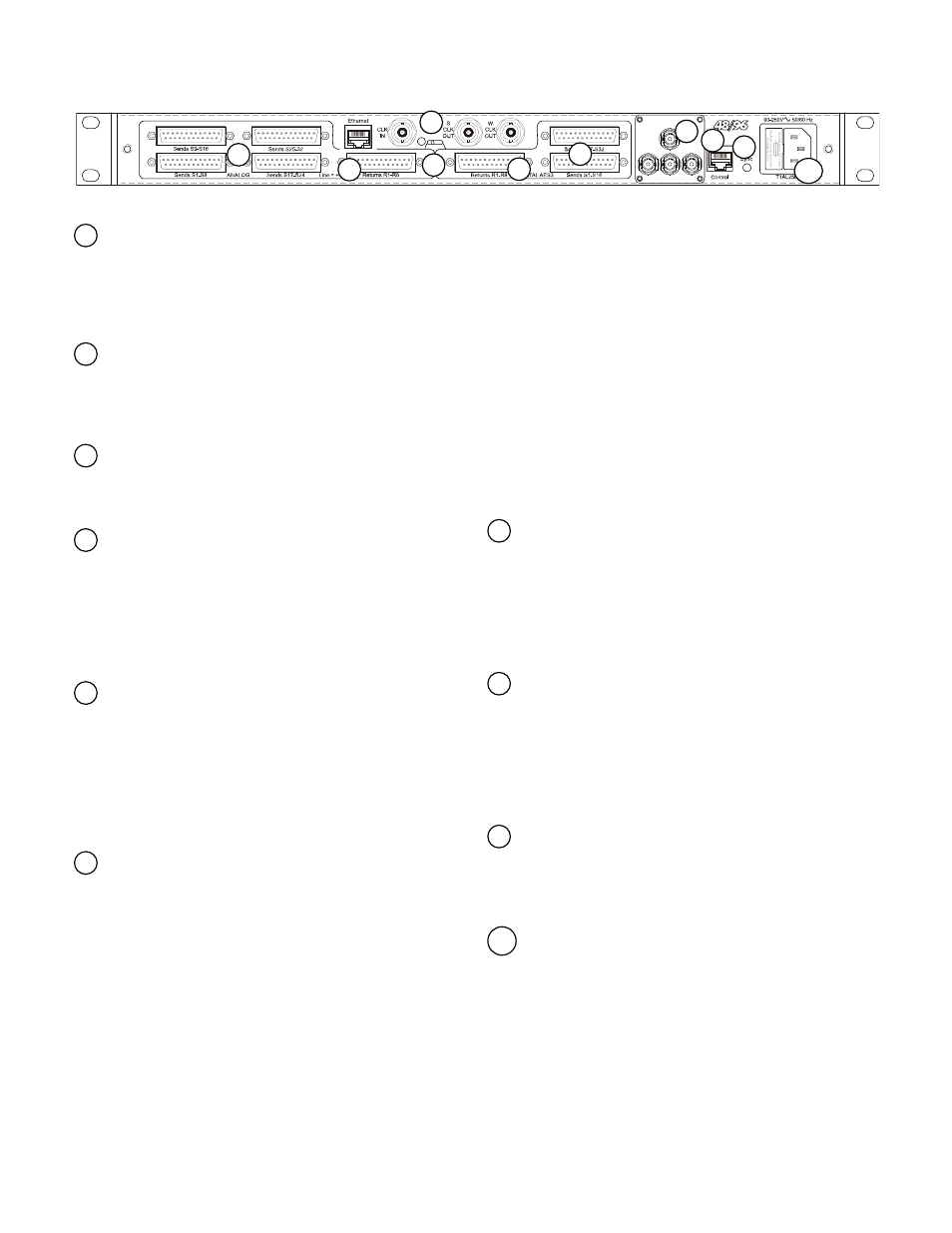
The Mixer Box – VIM‐1832
Analog Sends (outputs) ‐ Exiting the Mixer Box, the sends from
the Stage Box are grouped in 4 groups of 8. Each group is accessed
via DB‐25 to XLR “fan out” cables. DB‐25 TO 1/4” cables are also
available for use with mixers that only allow line level connection
through 1/4” jacks. Each send exits the Mixer Box at Line Level,
maximizing headroom on the console.
Analog Returns (inputs) ‐ The analog returns to the Stage box
are made via a single DB‐25 to XLR “fan out” cable. The DB‐25
connectors on both the Analog Sends and Returns utilize standard
DA‐88, TASCAM balanced pin‐out configuration. Connector pin‐outs
are illustrated in the Appendix.
Return Select Switch ‐ The 8 return channels are switch‐
selectable as EITHER analog OR digital. This selection is made via the
recessed switch in the center of the Mixer Box adjacent to the clock
connections.
Digital Returns (inputs) ‐ The digital returns to the Stage box
are made via a single DB‐25 to XLRF cable. These inputs MUST be
used in conjunction with the Clock I/O described below in either
master or slave mode. The DB‐25 connectors on both the Digital
Sends and Returns utilize a standard AES3 balanced pin‐out
configuration. Cable and connector pin‐outs are illustrated in the
Appendix. NOTE: The Analog DA‐88 cables are not pin compatible
with the digital cables.
Digital Sends (outputs) ‐ The sends from the stage box are
simultaneously available as AES3 digital signals. Connections are
made via 2 DB‐25 connectors, with 16 channels on each. Access to
the digital signal allows for connection to digital recorders or
consoles, bypassing their onboard converters and eliminating the
need for outboard converters. For digital connection straight into a
Yamaha PM5D, DM2000, DM1000 or M7CL, the optional VCB‐DDMY
and VCB‐DDMYIO cables connect directly to the Yamaha MY16AE
cards. Cables are available to connect to Pro Tools, or other devices.
Clock I/O ‐ By itself, the entire Light Viper system is internally
frequency coherent. The VIM‐1832 Mixer Box contains the clock
master for the system, and the Stage Box and any other send units
that are connected via the optical splits all sync to the clock
provided by the master. The LightViper 1832 system runs natively at
24 bit/ 96k, but can also run at 24 bit / 48k with a 48k clock input to
the “clock in” connector on the VIM‐1832.
The clock I/O is used when you need to synchronize with external
equipment making the entire system frequency coherent. When
using the digital returns the VIM MUST BE in either master or slave
mode with the equipment providing the digital input.
The Clock input will accept either “Word Clock” (96 KHz / 48 kHz) or
“Super Clock” (24.576 MHz / 12.288 MHz). Outputs are provided for
both clock types.
The system can operate in Slave Mode —In this mode clock is
supplied via the “clock in” connector overriding the internal clock.
The “clock outputs” are pass‐throughs for the clock connected to
the input.
In Master Mode there is nothing connected to the input and
external equipment is connected to the Clock Out, making the
internal clock the master in the system.
The LED next to the Clock In connector has three states to indicate
Status.
Off —No signal present on the Clock Input
Red
—Signal is present on the Clock Input but it is neither a valid
Word Clock nor Super Clock
Green
—There is either a valid Word Clock or Super Clock signal on
the Clock In
Fiber Connector ‐ The Mixer Box can be fit with ST connectors,
a single tactical grade TAC‐4 connector, or a Neutrik OpticalCon
connector. In live production use, it is recommended to fit the VIM‐
1832 and VIM‐1032 units with ST connectors, and utilize the VPL‐11,
12 or 13 panels containing 1, 2, and 3, TAC‐4 panel mount
connectors respectively. These connectors have ST pigtails which
connect with the mixer box ST connectors. Always be sure to use
appropriate fiber and compatible connectors.
Control Circuits Connector ‐ This RJ‐45 jack provides (3) bi‐
direction (mixer box to stage box) CMOS or TTL data lines (up to
38.4 KHz from Stage to FOH and 2MHz from FOH to Stage) plus
voltage and GND. THIS IS NOT AN ETHERNET CONNECTOR –
CONNECTING AN ETHERNET DEVICE TO THIS CONNECTOR COULD
DAMAGE THE DEVICE. The Pin‐Outs for this connector are detailed
in the Appendix. Most CMOS or TTL functions/equipment can be
adapted to make use of this connector.
Sync LED – This LED indicates the status of the fiber‐optic link
between the VIM‐1808 and VIM‐0808. It has three states; SOLID
RED indicates there is no sync present; ALTERNATING RED & GREEN
indicates the unit is searching for sync; SOLID GREEN indicates sync
is present (optical link) and OFF indicates no power.
Power Connector/Fuse ‐ Power to the Mixer Box is provided
with the supplied 3‐Prong IEC Power Cord. The internal power
supply can accept any voltage from 90‐260 at either 50 or 60Hz. The
power fuse is a 5x20mm, 1A Slo‐Blo. Only replace the fuse with an
exact match. If after replacement the fuse blows again, return the
unit for service.
10
9
8
7
6
5
4
3
2
1
1
2
3
4
5
6
7
8
9
10