Front indicators/connections – FiberPlex TD-1580 User Manual
Page 6
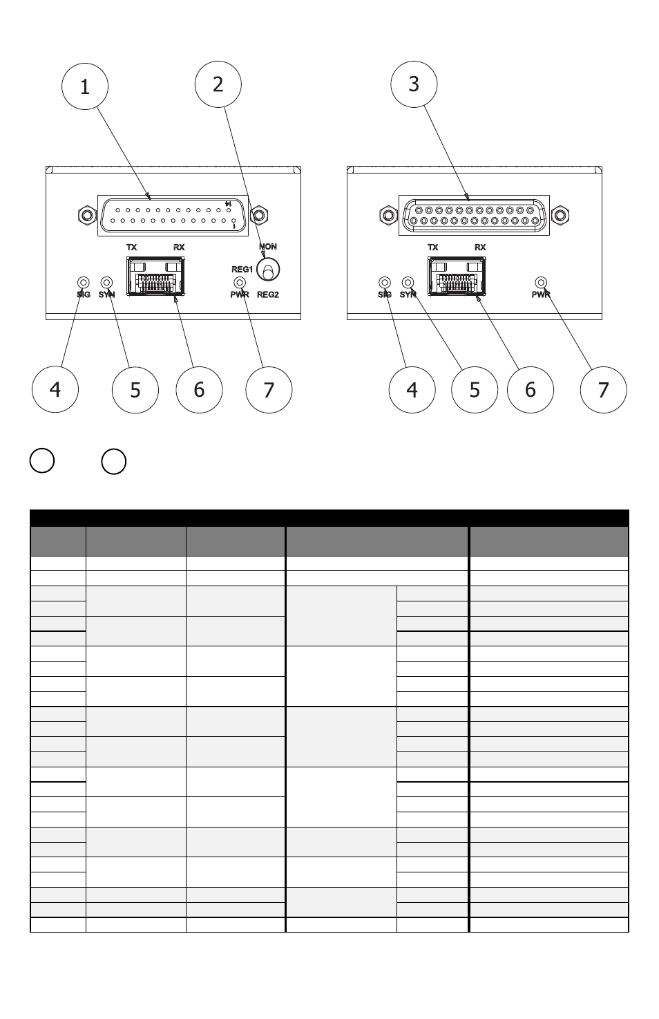
Front Indicators/Connections
Figure 1 TD‐1581 (left) and FOI‐1580 (right) Front Face
DCE &
DTE Connectors – Main data connections via D‐subminiature, 25‐position connector. The
DCE is a male (pins) and the DTE is a female (sockets) connector. Jackscrews are provided for securement. See
pinout below.
PINOUTS
Pin
FOI‐4451 (DCE)
Direction
FOI‐4541 (DTE)
Direction
6x4 Serial Configuration
EIA‐530 Configuration
1
Chassis Ground
Chassis Ground
7
Signal Ground
Signal Ground
2
Out
In
Channel 1 RS‐422
TX+
Send Data A (SD)
14
TX‐
Send Data B (SD\)
3
In
Out
RX+
Receive Data A (RD)
16
RX‐
Receive Data B (RD\)
4
Out
In
Channel 2 RS‐422
TX+
Request To Send A (RTS)
19
TX‐
Request To Send B (RTS\)
5
In
Out
RX+
Clear To Send A (CTS)
13
RX‐
Clear To Send B (CTS\)
20
Out
In
Channel 3 RS‐422
TX+
Terminal Ready A (TR)
23
TX‐
Terminal Ready B (TR\)
6
In
Out
RX+
Data Set Ready A (DSR)
22
RX‐
Data Set Ready B (DSR\)
24
Out
In
Channel 4 RS‐422
TX+
Terminal Timing A (TT)
11
TX‐
Terminal Timing B (TT\)
8
In
Out
RX+
Receive Timing A (RT)
10
RX‐
Receive Timing B (RT\)
15
In
Out
Channel 5 RS‐422
RX+
Send Timing A (ST)
12
RX‐
Send Timing B (ST\)
17
In
Out
Channel 6 RS‐422
RX+
Receiver Ready A (RR)
9
RX‐
Receiver Ready B (RR\)
18
Out
In
Channel 1 RS‐232
TX
Local Loopback (LL)
25
In
Out
RX
Test Mode (TM)
21
Out
In
Channel 2 RS‐232
TX
Remote Loopback (RL)
1
3