Power requirements and mounting, Rear indicators/connections, Surface mounting – FiberPlex TD-1580 User Manual
Page 8
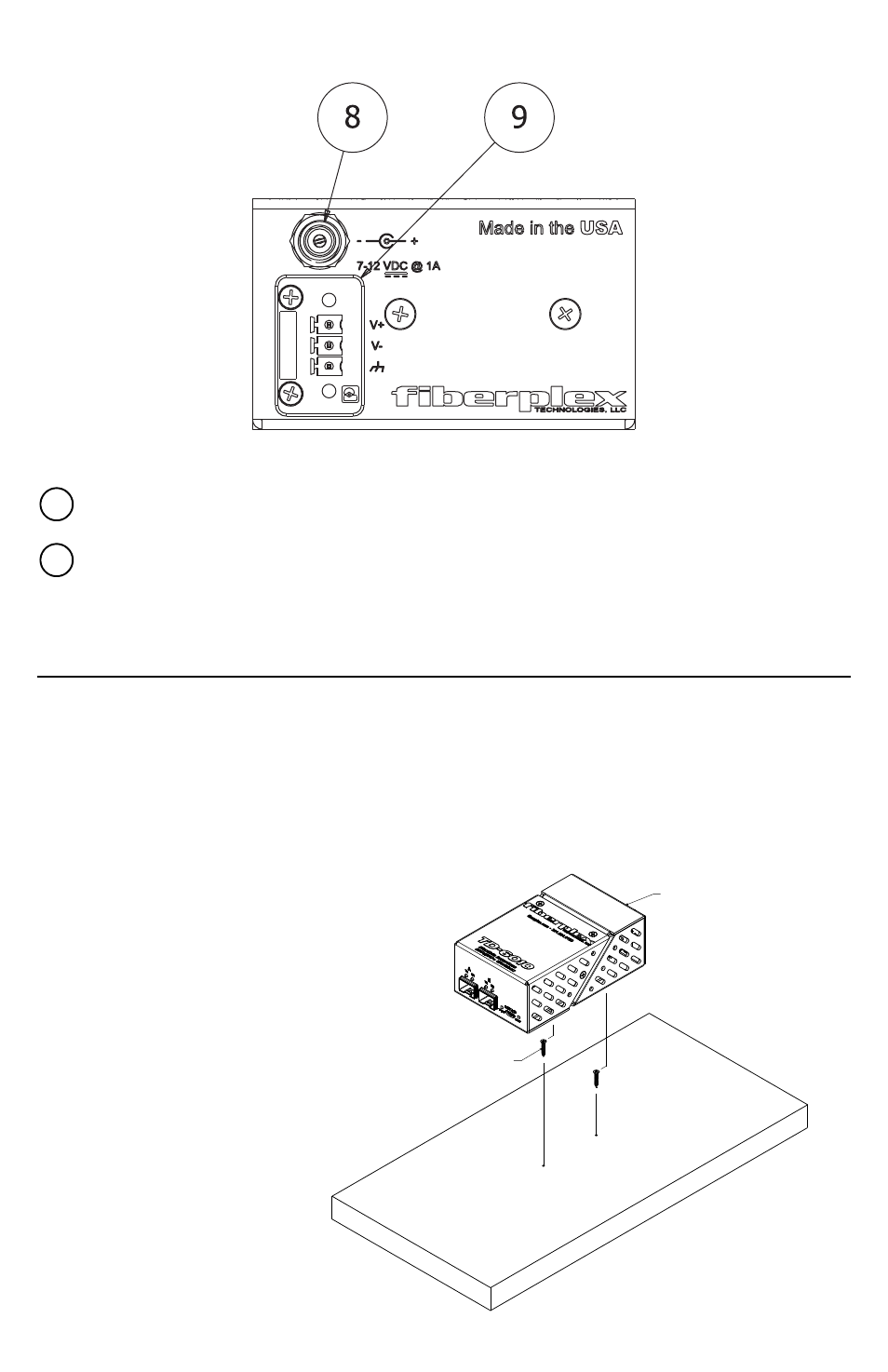
Rear Indicators/Connections
Figure 2 Rear Face
Circular DC Power Connection – DC power entry for the unit. This is a standard DC connection for use
with the included DC wall power adapter.
Phoenix DC Power Connection – Secondary power option. This is wired in direct parallel with the
Circular connector and has the addition of a positive earth chassis ground connection. This can be used
to power the unit on a client supplied power buss.
Power Requirements and Mounting
The TD‐1580 and TD‐1581 come with a 9V DC wall adapter for powering the units. Alternately, user supplied 7‐
28 VDC power can be used by utilizing the Phoenix power connector on the rear of the module.
IMPORTANT: For many serial data applications it is necessary to provide a positive earth ground reference
for proper serial operation. Earth ground can only be supplied using the Phoenix connector. DC power can
still be applied with the wall adapter in conjunction with just the earth ground on the Phoenix.
Surface Mounting
All TD modules have two keyhole mounting holes on the
bottom of the unit. Included with your packaging is a 1:1
scale template for spacing screws for surface
mounting. Simply transfer marks to the surface using
the template as a guide and secure the supplied
1/2” #2 wood screws leaving about 1/16”
below the head. Now, simply
lower the TD module over the
screw heads and slide to secure.
8
9
#2 Wood Screw, 1/2" Long, #1 Phillips
Drive
Lower TD Unit Over Screw
Heads,