Front indicators/connections – FiberPlex TIS-8632 User Manual
Page 6
Page 4
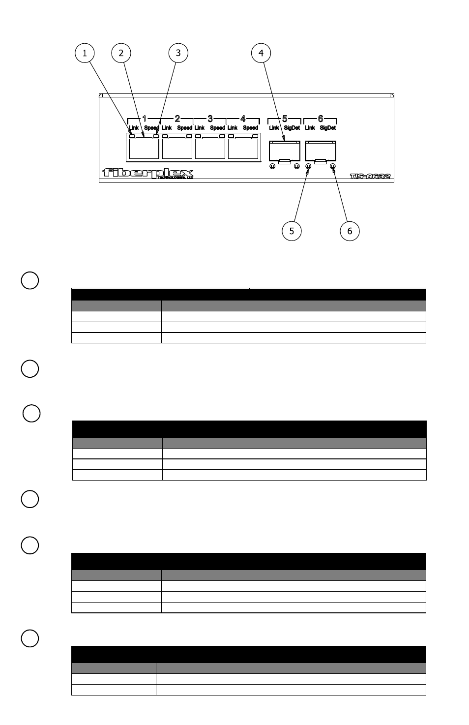
Front Indicators/Connections
Figure 1 TIS‐8632 Front Face
Cable Port LED, Upper Left – This LED, for each position, indicates status as per the following table;
Cable Port LED (Upper Left)
Status
Description
On
Link is OK
Off
No link present
Blinking
Data is being received or transmitted
Ethernet Cable Port (x4) – These jacks are Unshielded Twisted Pair RJ‐45 cable connection points for
Cat5 capability.
Cable Port LED, Upper Right – This LED, for each position, indicates status as per the following table;
Cable Port LED (Upper Right)
Status
Description
3 Blinks Repeating
1000M Speed
2 Blinks Repeating
100M Speed
1 Blink Repeating
10M Speed
SFP Slot (x2) – This is a standard MSA‐compliant SFP module slot. (See section ‘Inserting and Removing
SFP Modules’) These ports operate only at 1000 Base‐X rates. Do not connect both SFP ports of one unit to
both SFP ports of a second unit, this will cause a switching loop and the units will not operate properly.
SFP Slot LED, Lower Left– This LED, for each position, indicates status as per the following table;
SFP Slot LED (Lower Left)
Status
Description
ON
Fiber link is OK
OFF
Fiber link is failed
Blinking
Activity
SFP Slot LED, Lower Right – This LED, for each position, indicates status as per the following table;
SFP Slot LED (Lower Right)
Status
Description
ON
Optical signal detected
OFF
No laser input
1
2
3
4
5
6