Assembly – Fire Magic 2D-SSA Beverage Center User Manual
Page 5
REV 6 - 1402170710
L-C2-274
5
ASSEMBLY
PLUMB OR SET UP WASTE WATER DISPOSAL
The sink comes with a plastic trap and drainpipe extending
just below the sink (see Fig. 5-1).
A waste water container may be placed under the sink. It
must then be periodically checked and emptied when full.
Alternately, a permanent waste water drain may be plumbed
from under the sink out through the knock-out in the rear
left (stand alone only) or the enclosure (built-in only) to an
appropriate drain. Observe all locally applicable codes. If
required, remove the knock-out (stand alone only) by striking
it forcefully in the center with a mallet or other appropriate
tool. Observe all locally applicable codes.
ATTACH A WATER SOURCE (STAND ALONE)
The sink comes pre-installed and is plumbed so that a
garden hose or other pressurized water-supply line can
be connected to the female hose connector centered in
the lower end of the back of the unit (see Fig. 5-2). The
connector on the garden hose must be clean and free of
foreign material. Screw the end of the hose onto the female
hose connector.
ATTACH A WATER SOURCE (BUILT-IN)
Plumb a water line through the inside of the enclosure to
the
1
/
2
"
NPS connector attached to the faucet.
CONNECT THE STAND ALONE TO ELECTRICAL
POWER
To use the electrical outlets, blender, and electrical sockets
(stand alone only), the beverage center must be connected
to electrical power. This is performed by plugging in a
grounded electrical extension cord rated for outdoor use.
Plug the male end of the extension cord into an active
electrical outlet and the female end into the left-most
electrical connector on the right side of the unit (Fig. 5-3).
Other electrical devices may be plugged into the electrical
outlets on the right of the line-power hookup.
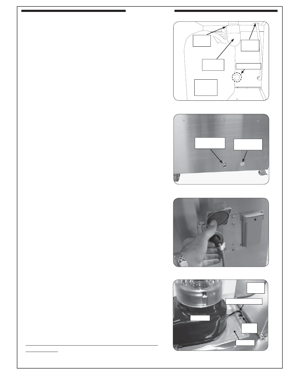
PLACE BLENDER IN BLENDER MOUNTING
Open the domed lid attached to the right rear of the
countertop. Unpack the blender and read the instructions.
Remove the tray located on top of the counter in front of
the domed lid. Then attach the provided plastic plug to the
blender electrical cord. Feed the cord through the cutout
that is located at the rear of the tray opening. Be sure to
snap the plastic plug in place. Then replace the tray. See
Fig. 5-4. From there, route the cord through the unit and to
the nearest grounded electrical outlet.
In the stand alone unit, the nearest outlet is located in the
right-side wall. Lower the cord towards the right-side wall
and then open the doors and remove the middle right-side
Female hose
connector
Waste water
knock-out
Blender
Knock-out
Waste
water
container
Drain
spout
Drain
clean-out
Faucet
base
Domed
lid
Cord into cutout
Plastic
plug
Fig. 5-1
Drain sink to container or drain line
Fig. 5-3
Electrical connectors (stand alone only)
Fig. 5-4
Blender placement (side view)
Fig. 5-2
Stand alone water hookup
Tray