6 fastener torques, 7 disassembly, Flowserve – Flowserve MEN User Manual
Page 30
MEN USER INSTRUCTIONS ENGLISH 71576288 - 02/13
Page 30 of 36
flowserve.com
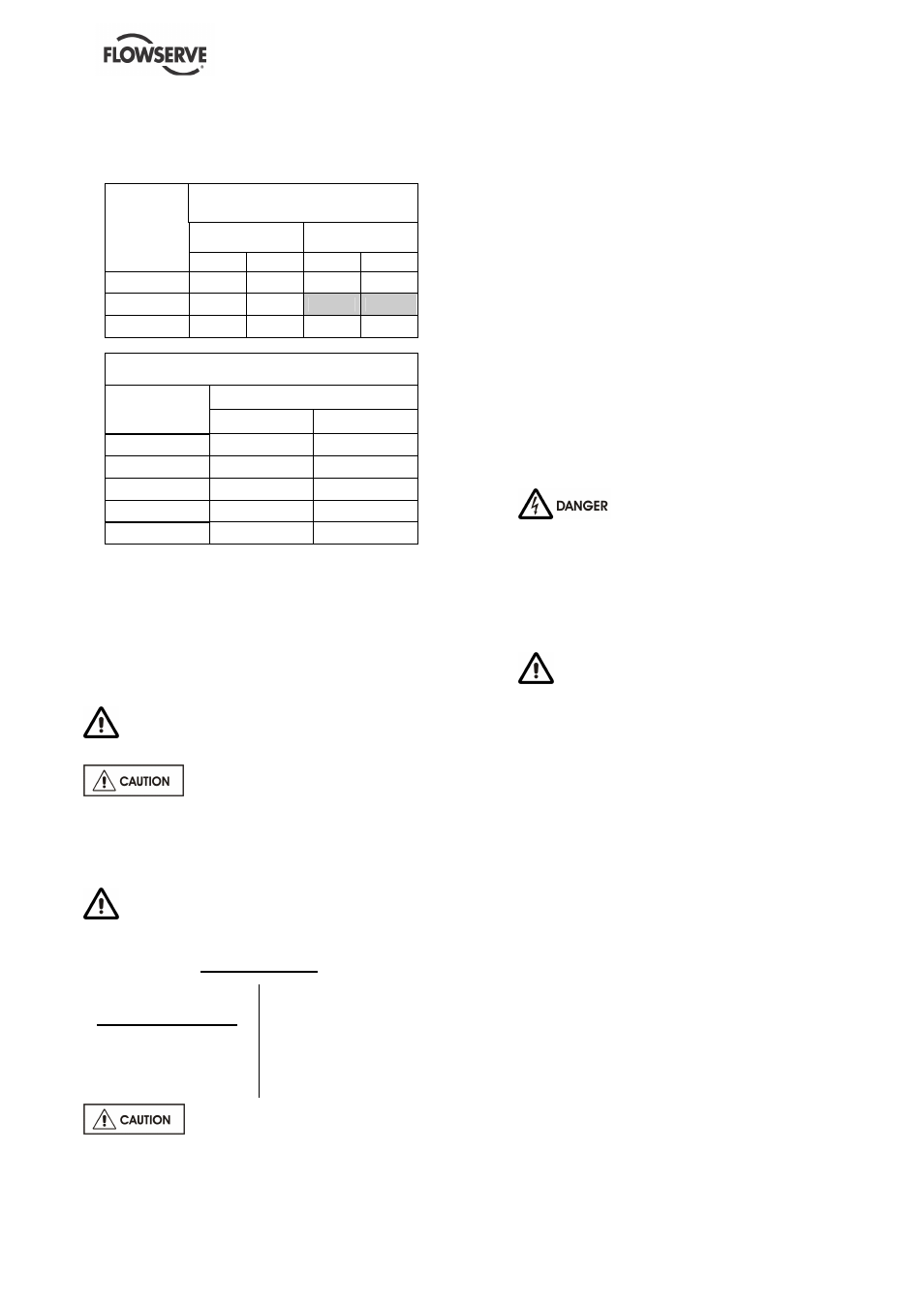
6.6 Fastener torques
The torques to be applied are:
SCREW
TORQUE
Casing / cover
Casing
cover/Bearing
m.daN
lbf.ft
m.daN
lbf.ft
HM 10
3
22
3
22
HM 12
5
37
HM 14
10
74
5
37
SHAFT END NUT
Diameter
Torque
m.daN
lbf.ft
M 12
6
44
M 14
8
59
M 18
12
89
M 20
14
103
M 24
16
118
The tightening torques have been calculated as a
function of the forces produced by the pumps.
These torques correspond to a tension of the shaft
end of 25 % to 50 % of the elastic limit.
The tolerance allowed on the tightening torques is
±
30 %.
6.7 Disassembly
Refer to section 1.6, Safety, and section 6
Maintenance, before dismantling the pump.
Before dismantling the pump for
overhaul, ensure genuine Flowserve replacement
parts are available. Refer to sectional drawings for
part numbers and identification.
REPAIR OF THE PUMP
If the pump presents abnormalities or a
persistent malfunction, contact immediately:
FLOWSERVE
Arnage - FRANCE
Memphis - USA
After-sales Service
Tel.: 1-(800)-343-7867
Fax.: 1-(901)-259-3946
Tel.: 02 43 40 57 57
(33) 2 43 40 57 57
Fax.: 02 43 40 58 17
(33) 2 43 40 58 17
Assembly and disassembly must
be carried out by Flowserve personnel or its
approved repairers whose list may be sent on
request.
It is obvious that the following instructions and
recommendations cannot replace their knowledge
and experience.
The pump should be disassembled only if certain
signs of anomalies or malfunction are observed.
Disassemble only to the extent that the problem
spot may be reached.
In any case, the disassembly must be carried out
by qualified personnel who have read the
instructions of the leaflet, and in particular the
safety instructions.
Disassembly must be done with great care to
avoid damage to the pumps internal parts. To
make reassembly easier, display parts in the
disassembly order. Protect all machined surfaces
from metal/metal contacts and from corrosion.
Before all disassembly it is imperative to:
a)
NEVER DO MAINTENANCE
WORK WHILST THE UNIT IS CONNECTED
TO POWER.
b) Close the outlet and inlet valve.
c) Wait until the pump casing is at ambient
temperature.
d) Be sure that the pump casing is not under
pressure.
e)
DRAIN PUMP AND ISOLATE
PIPEWORK BEFORE DISMANTLING THE
PUMP.
6.7.1 Dismantling of a MEN pump
6.7.1.1 Dismantling of a MEN pump with the
gland packing option
DISMANTLING OPERATIONS
a) Loosen the [6577-01] hexagon bolts (or [6577-
02]) for gripped casing cover with stuffing box)
and remove the complete rotor set.
b) Release the [2912] nut, remove the [2905]
plain washer, the [2250] radial flow impeller,
the [6700-02] key.
c) Loosen the [6577-02] hexagon bolts (if casing
cover with stuffing box is not gripped) and
remove the [1221] casing cover with the
complete seal ([4130], [4131], [4120], [6581],
[6572]).
d) Dismantling of packed gland:
Loosen the [6581] hexagon nut, remove the
[4120] gland flange, loosen the [6572] studs,
the [4131] follower in one part, the [4130]
gland packing. To dismantle the [2450] shaft
sleeve: heat the shaft sleeve up to 200 °C
(392 °F) to destroy the Loctite film.