Flowserve CPXS User Manual
Page 28
CPXS, CPXNS and CPXPS USER INSTRUCTIONS ENGLISH 71569250 07-11
Page 28 of 48
flowserve.com
6.8.4
Dismantling casing cover assembly
a) Loosen and remove the screws [6570.2]
holding the casing [1100] and casing cover
[1220] assembly together.
b) Pull the casing cover assembly out of the
casing and secure horizontally in a vice. On
some of the heavier assemblies it is advisable
to fit two studs into the top two holes in the
casing to temporarily support the casing cover,
whilst getting a firm grip.
c) Remove the 6mm hexagon socket head
containment shell capscrews [6570.1] and
washers.
d) Remove the containment shell(s) [224s] and
containment shell gasket [4590.2]. Discard the
gasket (and O-ring [4610] if dual containment).
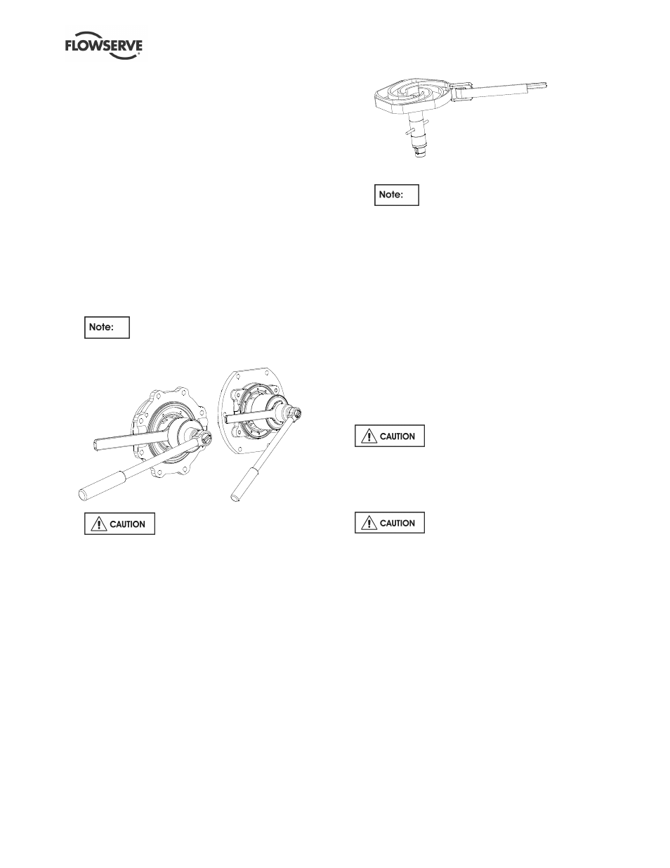
e) Loosen and remove the locknut [6580] using
the appropriate socket and spanner wrench
pair.
Locknut has left hand thread.
A handle extension may be required. See
section 6.5, Tools required, for proper sizes.
Frame 80
Frame 100 & 150
When removing the shaft nut,
residual fluid may be in the undercut.
f)
Rotate the inner rotor so that the shaft key
[6700.2] is at 12 o'clock position. Slide the
assembly [220] off the pump shaft and place in a
clean, non-ferrous area.
g) Remove the inner magnet assembly[220], key
[6700.2] and shims [3126] from the shaft.
h) Slide the shaft [2100.1], complete with impeller
[2200], out of the casing cover [1220].
i)
Inspect the coated surface of the shaft, or sleeves
[3400], if fitted. If damaged, it should be
replaced.
j)
The impeller/shaft assembly may now be
disassembled after first removing the sleeves
and spacer [2460.1], if fitted.
k) Secure the pump shaft [2100.1] in a vice in the
vertical position using soft jaws with a pin
through the bypass holes. Care must be
exercised so that the coating is not damaged.
l)
Loosen impeller [2200] using a strap wrench or
similar.
Right hand thread.)
m) Inspect BOTH sleeve bearing-bushings [3300s]
in the casing cover. Polishing in the bores and
thrust faces is normal. No removal is required.
n) If either bushing [3300s] appears to be
cracked, chipped or severely worn, remove by
laying the casing cover flat face uppermost.
o) Remove two setscrews [6570.6], if fitted. (See
drawings in section 8.5 and 8.6.)
p) Using an arbor, press out the bushings.
q) Remove tolerance rings [241s] and discard.
r) Remove the thrust collar [3610] from the inner
magnet rotor. The collar is a loose fit in the
carrier bore.
s) Remove the thrust collar gasket [4590.5], discard
and replace.
6.9 Examination of parts
Used parts must be inspected
before assembly to ensure the pump will
subsequently run properly.
In particular, fault diagnosis is essential to enhance
pump and plant reliability.
THE MAGNETS MUST BE KEPT AT A
SAFE DISTANCE FROM OTHER PARTS AND
TOOLS.
a) Clean the internal pump parts thoroughly.
b) Inspect for excessive wear, pitting, corrosion,
erosion or damage and any sealing surface
irregularities. Replace as necessary.
c) For units equipped with a wash flow strainer,
be sure to clean the filter removing any debris
that may be blocking the strainer holes.
d) Clean lubrication holes in the casing cover
[1220], inner magnet carrier [220] and shaft
[2100.1].
e) On the casing cover, inspect the injection, vent,
drain and return holes. Clean if necessary.
f) The balance holes of the inner rotor should
also be inspected and cleared of any debris.
g) Replace all gaskets [4590s] and O-rings
[4610s].