10 magnets, 11 assembly – Flowserve CPXS User Manual
Page 29
CPXS, CPXNS and CPXPS USER INSTRUCTIONS ENGLISH 71569250 07-11
Page 29 of 48
flowserve.com
h) Ensure all lubrication passageways in the
bearing housing are clean and free from
damage.
i)
Check the driver manufacturer's instructions.
As a minimum, check the bearings and shaft
for straightness.
j)
The lubricant, bearings and bearing seals in
the motor should be inspected for
contamination and damage.
6.10 Magnets
Demagnetization of the magnet material can be the
result of either high operating temperatures around
the magnet assemblies or decoupled magnets
operating around a metallic containment shell.
High ambient temperatures are detrimental to the
attraction properties of the magnets.
The inner magnet assembly is most susceptible to
high operating temperatures and cannot tolerate
operation above its upper critical temperature limit.
If decoupling has occurred or if a system
upset has caused the temperature limits to be
exceeded, the original strength of the magnets may
have decreased. The following torque test
procedure should be followed in such a situation.
6.10.1.1 Magnet torque test procedure
a) Remove the casing [1100] from the pump.
b) Secure the bearing housing on a stable
worktable.
c) Lock the outer rotor assembly [230] in position.
Insert bolt in assembly hole.
d) Remove the impeller [2200] by using a strap
wrench around the periphery of the impeller.
Turn counterclockwise.
e) Install a shaft adapter on the shaft [2100.1]
threaded connection.
•
Models 80 and 100
M22 -1.5 pitch
•
Model 150
M30 -1.5 pitch
f) Use a torque wrench on the shaft adapter nut
and turn clockwise to measure the force
required to break the magnetic coupling.
Adjust the wrench setting such that the torque
value is determined prior to breaking the
magnetic couple. This is the torque capability
of the magnetic coupling.
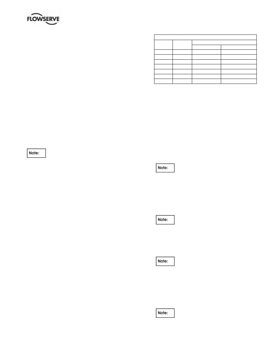
Factory torque specification
Minimum torque Nm (lbf•ft)
Model
Series
Neodymium
Samarium cobalt
80
8
13 (9.6)
11 (8.1)
80
15
27 (20)
24 (17.7)
100
25
45 (33)
40 (29.5)
100
50
90 (66)
80 (59)
150
50
80 (59)
70 (51.5)
150
100
160 (118)
140 (103)
150
150
240 (177)
210 (154.5)
6.11 Assembly
To assemble the pump consult the sectional
drawings. See section 8, Parts lists and drawings.
Ensure threads, gasket and O-ring mating faces
are clean. Apply thread sealant to non-face sealing
pipe thread fittings.
6.11.1 Outer assembly - bearing housing
assembly
a) If removed, replace the skid ring [252].
b) If the radial ball bearings [3011s] are found to
be damaged, remove the damaged ones and
press two new bearings onto the shaft.
Be sure to press on only the inner
race of the bearing whilst pressing it onto the
shaft [2100.2]. Press bearings up to the shaft
shoulders.
c) Install the bearing/shaft assembly into the bore
of the bearing housing [3200].
d) Seat the end cover gasket [4590.4].
e) Bolt bearing end cover [3260] to bearing
housing face with screws [6570.4].
Be sure that the oil return grooves on
the gasket and end cover line up.
f) Tighten screws crosswise to 13 Nm (9.6 lbf•ft)
torque.
g) Turn the shaft coupling end to ensure freedom
of rotation.
h) Install the flinger [2540] over the shaft.
Be sure that the flinger is not pressed
down hard against the bearing end cover.
i)
Position the bearing housing [3200]
horizontally.
j)
Coat the outer magnet rotor threads with anti-
seize compound.
k) Insert outer magnet rotor [230] into the large bore
of the bearing housing and screw onto the frame
shaft.
Right hand thread.