Flowserve CPXS User Manual
Page 30
CPXS, CPXNS and CPXPS USER INSTRUCTIONS ENGLISH 71569250 07-11
Page 30 of 48
flowserve.com
l)
Insert a bar or screw into the holes provided in
the bearing housing and outer rotor to lock the
rotor.
m) Place a coupling hub and key onto the shaft
[2100.2] coupling end and torque the outer
magnet assembly crosswise to 54 Nm (40
lbf•ft).
n) Remove the bar or screw and check shaft for
freedom of rotation.
o) Re-install the pipe plug.
6.11.2 Inner assembly - casing cover assembly
a) If the sleeve bearing bushings [3300s] were not
removed during dismantling, proceed to Rotor
assembly, section 6.11.3.
b) The inboard tolerance ring [241.1] must be
trimmed to length using tin snips. This is due to
the difference in diameter of the two bushings.
Trim off three corrugations prior to placement in
the casing cover [1220].
c) There must be a minimum gap of 1.5 mm (0.06
in.) between the cut ends of the tolerance ring
before assembly of bushes.
d) Install the cut tolerance ring into the inner bore.
Rotate the ring to guarantee it is
secure.
e) Position the casing cover with "top" designation
at 12 o'clock position.
f) Insert the front bearing bushing [3300.1] so that
the lubrication groove is at a 9 o'clock position.
The face with the white spot should be visible.
The opposite face is lapped and should locate
against the shoulder in the casing cover.
g) Press in the front bearing bushing up to the
shoulder in the casing cover.
h) Fit bearing bush spacer [2460.2] (if appropriate).
i)
Insert the second tolerance ring [241.2], rotating it
for a secure fit.
j)
Insert rear bearing bushing [3300.2] until
resistance is felt.
k) Position the bushing so that one lubrication
groove is at the 6 o'clock position and press in
up to the shoulder in the casing cover. The
face with the white spot should mate up to the
shoulder in the casing cover.
l)
If a bearing bush spacer has been fitted, secure
with two radial socket head setscrews [6570.2].
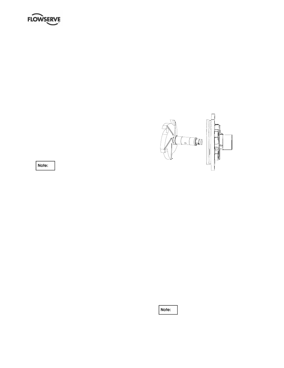
6.11.3 Rotor assembly
a) Thoroughly clean and degrease impeller and
shaft threads.
b) Install the impeller [2200] on the pump shaft
[2100.1], after first applying anti-seize
compound (which does not contain copper) at
the impeller to shaft thread to assist in
subsequent removal.
c) Secure the pump shaft in a vice in the vertical
position using soft jaws with a pin through the
bypass holes. Care must be exercised so that
the coating is not damaged.
d) Tighten the impeller using a strap wrench or
similar.
e) If fitted, slide sleeves [3400] and spacer
[2460.1] onto shaft.
f) Position the casing cover [1220] upright with
the through bore in the horizontal plane and
"TOP" designation at 12 o'clock.
g) Slide the shaft [2100.1] through the casing
cover.
h) Diametral journal bearing clearances are 0.08
to 0.13 mm (0.003 to 0.005 in.). Extreme care
must be exercised.
i)
Place the thrust collar gasket [4590.5] into the
inner rotor.
j)
Make sure it is fitted over the drive pin [2923],
which should be replaced if damaged.
k) If a new pin is fitted it must be ensured it does
not protrude more than 3 mm (0.12 in.) from
inner rotor face. The top of the pin should not
foul the silicon carbide thrust face. Shorten if
necessary.
l)
Install the thrust collar [3610] into the inner rotor.
Be sure that the slot in the thrust collar is in
alignment with the drive pin. Small spots of
grease may be used to hold the gasket and collar
in place, if necessary.
m) Install 0.8 mm (0.032 in.) shim [3126] on the
pump shaft, between inner rotor and shaft
shoulder.
n) Install the inner rotor key [6700.2].
o) Slide the inner rotor [220] onto the shaft -pump
end.
p) Thread the locknut [6580] onto the shaft-pump
end.
Left hand threads.
q) Check the setting of impeller clearance, see
section 6.7, Setting of the impeller clearance.