Flowserve CPXM User Manual
Page 10
CPXM and CPXRM USER INSTRUCTIONS ENGLISH 71569101 10-08
Page 10 of 32
flowserve.com
The pump may be stored as above for up to 6
months. Consult Flowserve for preservative actions
when a longer storage period is needed.
2.5 Recycling and end of product life
At the end of the service life of the product or its
parts, the relevant materials and parts should be
recycled or disposed of using an environmentally
acceptable method and local requirements. If the
product contains substances that are harmful to the
environment, these should be removed and disposed
of in accordance with current regulations. This also
includes the liquids and/or gases that may be used in
the "seal system" or other utilities.
Make sure that hazardous substances are
disposed of safely and that the correct personal
protective equipment is used. The safety
specifications must be in accordance with the current
regulations at all times.
3 DESCRIPTION
3.1 Configurations
The pump is a modular designed centrifugal pump
that can be built to achieve almost all chemical liquid
pumping requirements. (See 3.2 and 3.3 below.)
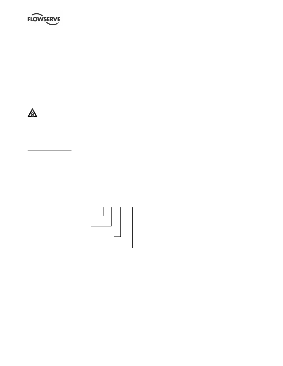
3.2 Name nomenclature
The pump size will be engraved on the nameplate
typically as below:
80-50CPXM200
Nominal suction size in mm
Nominal discharge size in mm
Configuration – see 3.3.1 and 3.3.2 below
Nominal ISO maximum impeller diameter
The typical nomenclature above is the general guide
to the CPXM configuration description. Identify the
actual pump size and serial number from the pump
nameplate. Check that this agrees with the
applicable certification provided.
3.3 Design of major parts
3.3.1 Pump casing
The pump casing is designed with a horizontal
centreline end inlet and a vertical centreline top outlet
which makes it self venting.
For ease of maintenance, the pump is constructed so
that pipe connectors do not have to be disturbed
when internal maintenance is required.
3.3.2 Impeller/stubshaft
An open impeller with integral stubshaft is fitted.
(On the CPXRM the impeller is recessed into the
back of the casing with a wide front clearance.)
3.3.3 Adjustment stud
The adjustment stud is screwed into the end of the
motor shaft. Adjustment of impeller front clearance is
achieved by rotating the stubshaft on this stud.
3.3.4 Muff coupling
The muff coupling is investment cast in two halves
(WCB steel). Notches at 30 degree increments around
the circumference of the coupling assist in setting the
impeller face clearance.
3.3.5 Pump bearings and lubrication
The pump uses the motor bearings to support and
position the pump shaft. See motor instruction book
for lubrication details.
3.3.6 Seal housing
The seal housing has spigots between the motor
pedestal and bearing housing for optimum concentricity.
A fully confined gasket forms the seal between the
pump casing and the seal housing.
The seal housings designs provide improved
performance of mechanical seals.
The design enables one of a number of sealing
options to be fitted.
3.3.7 Shaft seal
The mechanical seal(s) attached to the stubshaft seals
the pumped liquid from the environment.
3.3.8 Driver
The driver is a close-coupled electric motor featuring
bearing location. This provides positive rotor assembly
location to limit axial movement and allow accurate
impeller setting.