Flowserve CPXM User Manual
Page 20
CPXM and CPXRM USER INSTRUCTIONS ENGLISH 71569101 10-08
Page 20 of 32
flowserve.com
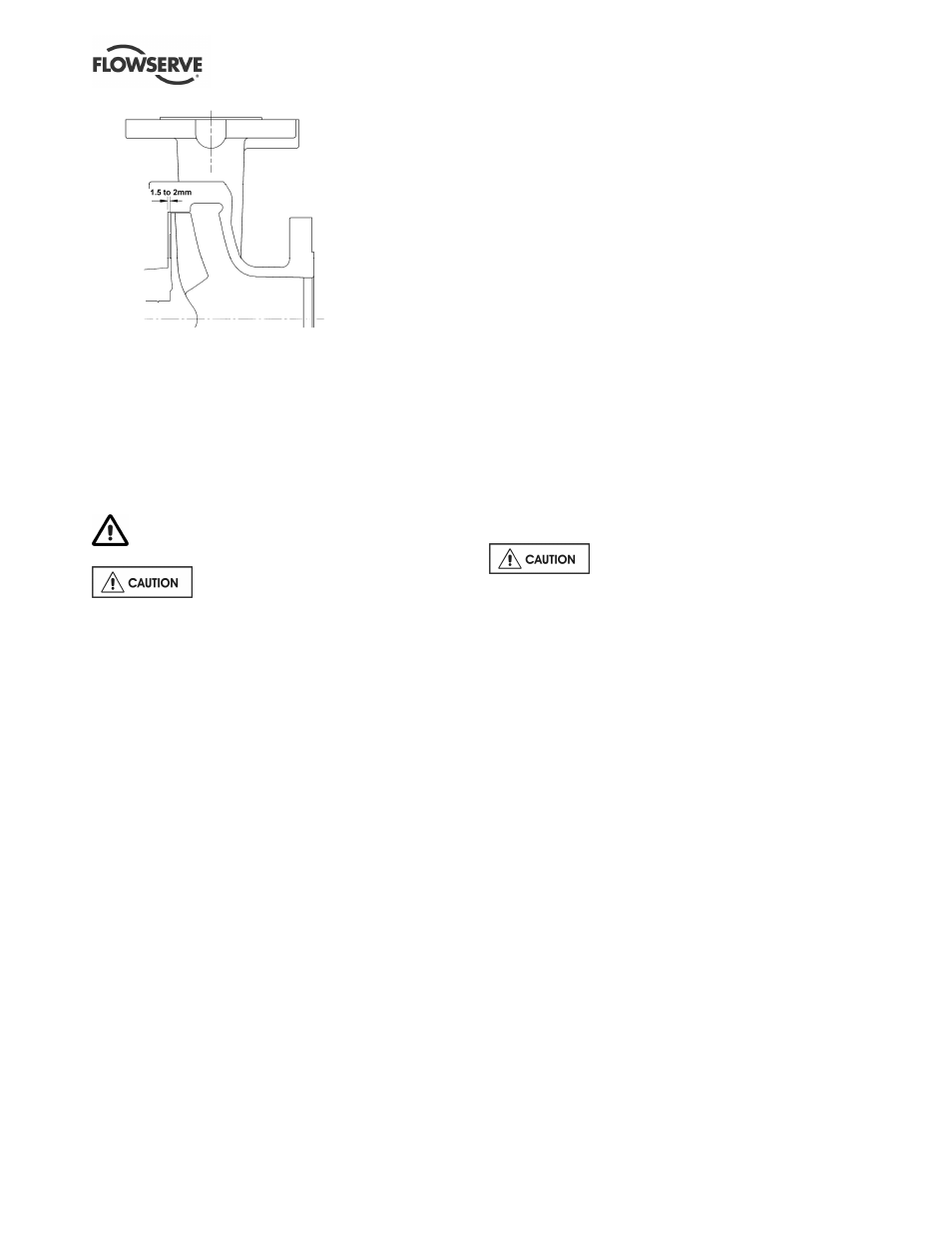
g) Carefully loosen and back off the grubscrew and
tighten the coupling bolts, ensuring that the gap
is equal between the coupling halves.
h) Torque the screws to the specified values:
M 8 - 30 Nm (22 lbf•ft)
M 10 - 58 Nm (43 lbf•ft)
i)
If a cartridge seal is fitted it should be reset at this
point.
6.8 Disassembly
Refer to Safety section before dismantling the
pump.
Before dismantling the pump for
overhaul, ensure genuine Flowserve replacement
parts are available.
Refer to sectional drawings for part numbers and
identification. See section 8, Parts lists and drawings.
6.8.1 General
a) Close suction and discharge valves and drain
liquid from the pump.
b) Remove screws from pump casing and pull motor
complete with rotating assembly from back of
pump casing, which will be left connected in
position in the pipework.
c) Unclip the coupling guards.
d) Take out the muff coupling screws and remove
coupling.
6.8.2 Pumps with single seals
a) Prevent the motor shaft from rotating.
b) Carefully rotate the impeller in an anti-clockwise
rotation, whilst supporting the impeller, until it
releases from the adjustment stud. Take care
not to damage the seal.
c) Withdraw the impeller/stubshaft assembly,
complete with mechanical seal, from the seal
housing.
d) Release the tension in the mechanical seal. The
seal manufacturer's instructions should be
followed for dismantling and assembling the seal.
e) Remove seal housing bolts and withdraw the seal
housing from the bracket.
6.8.3 Pumps with double mechanical seals
a) Remove the nuts retaining the seal housing to
the bracket.
b) Carefully rotate the impeller in an anti-clockwise
direction whilst supporting the impeller and seal
housing. The integral impeller and stub shaft
combined with the seal housing will release from
the unit as a sub-assembly. (Large pump sizes
have a tapped hole for fitting a lifting eye to assist
with this procedure.)
c) Remove the nuts from the seal cover to gain
access to the seals. Release the tension in the
mechanical seals.
d) The seal manufacturer's instructions should be
followed for dismantling and assembling the seal.
e) The mounting bracket can now be removed from
the motor after first removing the fixing screws.
f) The adjustment stud in the motor shaft can be
removed using two M 8 nuts.
6.9 Examination of parts
Used parts must be inspected before
assembly to ensure the pump will subsequently run
properly. In particular, fault diagnosis is essential to
enhance pump and plant reliability.
6.9.1 Casing, seal housing and integral impeller/
stubshaft assembly
Inspect for excessive wear, pitting, corrosion, erosion
or damage and any sealing surface irregularities.
Replace as necessary.
6.9.2 Integral impeller/stubshaft
Replace if the shaft is grooved or pitted or if the
impeller vanes are eroded or damaged.
6.9.3 Gaskets
After dismantling, discard and replace. (If the pump
seal arrangement has a lip seal, it should be replaced
at overhaul.)
6.9.4 Motor
Check the motor shaft for free rotation and absence
of bearing noise or shaft 'float'. If necessary, have
the motor serviced by a specialist or replace with a
Flowserve approved type.