6 electrical connections – Flowserve CPXM User Manual
Page 14
CPXM and CPXRM USER INSTRUCTIONS ENGLISH 71569101 10-08
Page 14 of 32
flowserve.com
Seal housings/covers having an auxiliary quench
connection, require connection to a suitable source of
liquid flow, low pressure steam or static pressure from
a header tank. Recommended pressure is 0.35 bar
(5 psi) or less. Check General arrangement drawing.
Double seals require a barrier liquid between the
seals, compatible with the pumped liquid.
With back-to-back double seals, the barrier liquid
should be at a minimum pressure of 1 bar (14.5 psi)
above the maximum pressure on the pump side of
the inner seal. (See chart.) The barrier liquid
pressure must not exceed limitations of the seal on
the atmospheric side. For toxic service the barrier
liquid supply and discharge must be in a safe area.
Special seals may require modification to auxiliary
piping described above. Consult Flowserve if unsure
of correct method or arrangement.
For pumping hot liquids, to avoid seal damage, it is
recommended that any external flush/cooling supply
be continued after stopping the pump.
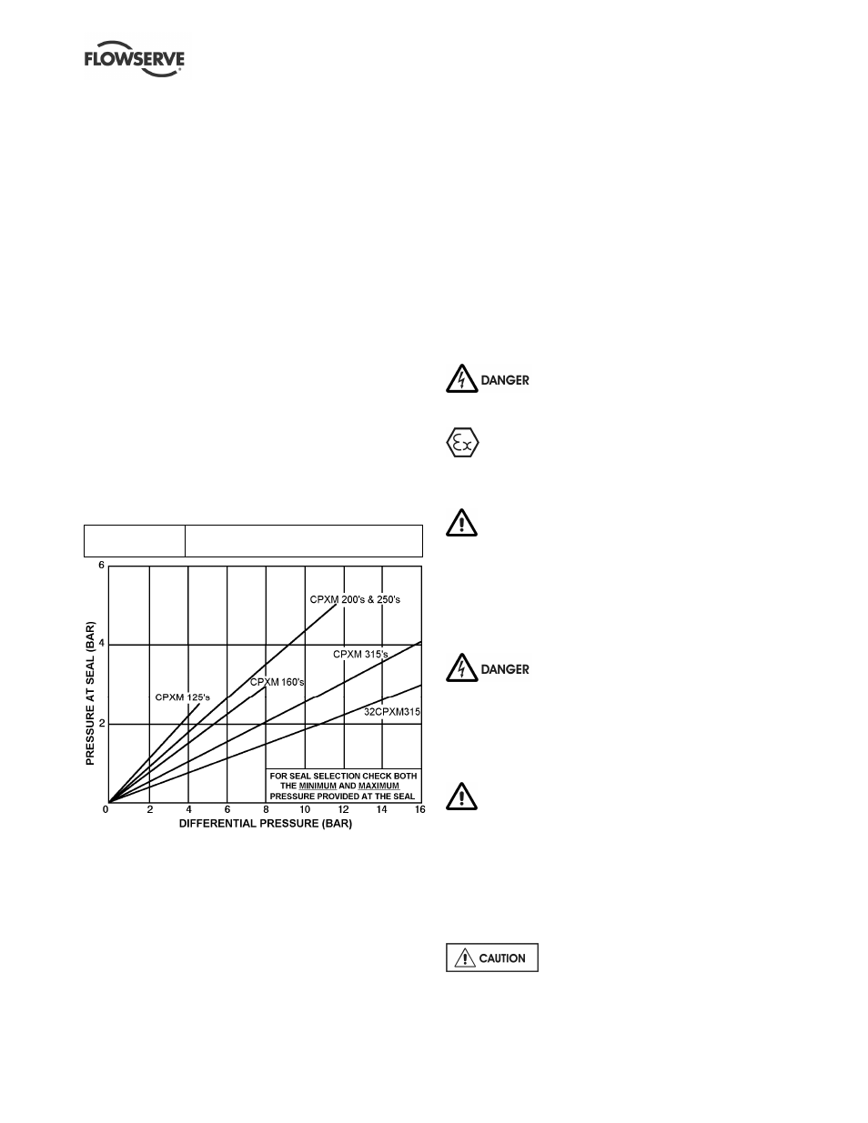
Seal chamber pressure v generated head:
Mechanical seal
Use seal manufacturer's limits or ask seal
manufacturer to verify seal pressure
Notes:
a) Total seal pressure is equal to pressure at seal plus suction
pressure.
b) For pumped liquid viscosities greater than 440 Centistokes
multiply the generated pressure by 1.25 for 125, 160 and 200
size pumps and by 2.0 for larger sizes.
c) Differential pressure in bar equals head in metres multiplied by
specific gravity all divided by 10.19.
d) Ensure to check the seal minimum and maximum seal
pressure limits are not exceeded and the pressure is agreed
with Flowserve.
4.5.5.2 Pumps fitted with heating jackets
Connect the heating pipes from the site supply. The top
connection should be used as the outlet to ensure
complete filling/venting of the annulus with heating
liquids. Steam is usually in at the top, out at the bottom.
4.5.5 Final checks
After connecting piping to the pump, rotate the shaft
several times by applying gentle pressure on the motor
fan to ensure there is no binding and all parts are free.
Check the tightness of all bolts in the suction and
discharge pipework. Check also the tightness of all
foundation bolts.
4.6 Electrical connections
Electrical connections must be made
by a qualified Electrician in accordance with relevant
local national and international regulations.
It is important to be aware of the EUROPEAN
DIRECTIVE on potentially explosive areas where
compliance with IEC60079-14 is an additional
requirement for making electrical connections.
It is important to be aware of the EUROPEAN
DIRECTIVE on electromagnetic compatibility when
wiring up and installing equipment on site. Attention
must be paid to ensure that the techniques used during
wiring/installation do not increase electromagnetic
emissions or decrease the electromagnetic immunity of
the equipment, wiring or any connected devices. If in
any doubt contact Flowserve for advice.
The motor must be wired up in
accordance with the motor manufacturer's
instructions (normally supplied within the terminal
box) including any temperature, earth leakage,
current and other protective devices as appropriate.
The identification nameplate should be checked to
ensure the power supply is appropriate.
A device to provide emergency stopping must
be fitted.
If not supplied pre-wired to the pump unit, the
controller/starter electrical details will also be supplied
within the controller/starter.
For electrical details on pump sets with controllers
see the separate wiring diagram.
See section 5.4, Direction of rotation
before connecting the motor to the electrical supply.