4 performance and operating limits, 4 installation, 1 location – Flowserve CPXM User Manual
Page 11
CPXM and CPXRM USER INSTRUCTIONS ENGLISH 71569101 10-08
Page 11 of 32
flowserve.com
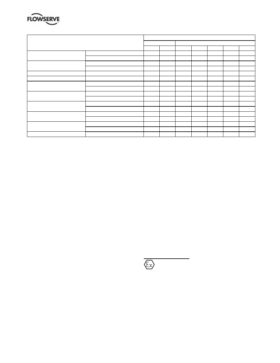
Motor frame size
Flange mounted
Foot/flange mounted
Motor manufacturer and type
80
90
100/112
132
160
180
200
TECO standard
Standard motor acceptable?
Yes
No
No
Yes
Yes
Yes
Yes
'AEBB'
With alternative 2A grease?
N/A
Yes (1) Yes (1)
N/A
N/A
N/A
N/A
TECO
Standard motor acceptable?
No
No
No
No
No
-
-
aluminium range
With drive end bearing location?
Yes
Yes
Yes
Yes
Yes
-
-
ABB standard 'M2AA'
Standard motor acceptable?
Yes
Yes
Yes
Yes
Yes
Yes
Yes
LEROY SOMER standard 'LSB 5'
Standard motor acceptable?
Yes
Yes
Yes
Yes
Yes
Yes
Yes
ELECTRODRIVES
Standard motor acceptable?
No
No
No
No
Yes
Yes
Yes
standard 'ALPAK'
With drive end bearing location?
Yes (2)
Yes (2) Yes (2)
Yes (2)
N/A
N/A
N/A
BROOK HANSEN
Standard motor acceptable?
No
No
No
No
No
No
No
standard 'ARGUS'
With drive end bearing location?
Yes
Yes
Yes
Yes
Yes
Yes
Yes
SIEMENS
Standard motor acceptable?
No
No
No
No
Yes
Yes
Yes
standard 'LA'
With drive end bearing location?
Yes
Yes
Yes
Yes
N/A
N/A
N/A
VEM
Standard motor acceptable?
No
No
No
No
No
No
No
Standard 'K21R'
With drive end bearing location?
Yes
Yes
Yes
Yes
Yes
Yes
Yes
GAMAK
Standard motor acceptable?
No
No
No
No
No
No
No
Standard 'AGM'/'AG'
With drive end bearing location?
Yes
Yes
Yes
Yes
Yes
Yes
Yes
WEG 'W21' cast iron
Standard motor acceptable?
Yes
Yes
Yes
Yes
Yes
Yes
Yes
Notes: N/A = Not applicable.
1) The standard grease used on TECO motor frames 90, 100 and 112 is unsuitable as it does not generate sufficient lubricating film
thickness with the relatively low viscosity 5K grease. The alternative grease 2A is acceptable and must be specified.
2) Standard ALPAK motor frames 80 to 132 inclusive have bearings at the non-drive end with a special retention device. This device is not
acceptable for use with the CPXM unit. The ALPAK machine with bearing cap locating the drive end bearing is acceptable.
A wide range of electric motors have been tested and
approved for use with CPXM units. The table lists
acceptable motors and indicates whether the
standard motors are approved or if a modification is
required.
The position of the terminal box can be changed by
rotating the complete motor. To do this on motor frames
80 and 90, remove the fasteners from the motor flange,
rotate the motor and re-fit the fasteners. For motor
frames 100 and above, with multi-positioned feet, also
unbolt the feet and refit in the appropriate position.
3.3.9 Accessories
Accessories may be fitted when specified by the
customer.
3.4 Performance and operating limits
This product has been selected to meet the
specifications of the purchase order. See section 1.5.
The following data is included as additional
information to help with your installation. It is typical,
and factors such as temperature, materials, and seal
type may influence this data. If required, a definitive
statement for your particular application can be
obtained from Flowserve.
3.4.1 Operating limits
3.4.1.1 Temperature limits of working fluids
Horizontal units: -20 ºC (-4 ºF) to +160
ºC (320 ºF).
Vertical units: -20 ºC (-4 ºF) to +120 ºC (248 ºF).
(These limits subject to approved mechanical seal
area design.)
3.4.1.2 Ambient temperature
These units are normally fitted with TEFC motors
suitable for an ambient temperature up to 40 ºC
(104 ºF). Specific pumps may be fitted with motors to
suit client's requirements with other ambient
temperature limits - see motor nameplate for details.
4 INSTALLATION
Equipment operated in hazardous locations
must comply with the relevant explosion protection
regulations. See section 1.6.4, Products used in
potentially explosive atmospheres.
4.1 Location
The pump should be located to allow room for access,
ventilation, maintenance and inspection with ample
headroom for lifting and should be as close as
practicable to the supply of liquid to be pumped. Refer
to the general arrangement drawing for the pump set.