8 examination of parts – Flowserve ERPN-M User Manual
Page 28
ERPN-M USER INSTRUCTIONS ENGLISH 02-08
Page 28 of 37
6.7.3 Dismantling of the inner rotor
1) Loose both socket screws [042] and pull out casing
cover inclusive inner rotor [M01] of magnet
coupling, impeller shaft [417] and impeller [425] out
of pump casing [360].
2) Remove casing gasket [398] from pump casing
[360].
The casing gasket [398] shall be
renewed after each disassembly. Now the inner
rotor can be dismantled.
3) Place inner rotor assembly vertically on impeller
[425] and unscrew socket screw [043] and pull off
can [M03] upwards and then remove O-ring [507]
from casing cover [370].
4) Unscrew socket screw [M08] and pull carefully the
inner rotor [M01] from axial bearing [M06].
5) Now detach the non-positive connections of locking
plate [4174], screw hex screw out of shaft [417] and
remove locking plate [4174] and washer [4172].
Take care of inner rotor [M01]
of magnetic coupling so that the magnets will not
be damaged.
6) Loosen socket screw [041] to pull radial bearing
[M04], axial bearings [M05] and [M06], shaft sleeve
[M07] from shaft [417] respectively casing cover
[370].
7) As next step pull casing cover [370] inclusive
casing wear ring [367] from impeller [425] and turn
the impeller shaft [417] inclusive impeller [425] by
180°.
8) Unsecure locking plate [454] and loose impeller nut
[456] (right hand thread).
Pumps having a screwed inducer
have no impeller nut. Therefore loose the inducer.
Pumps having a slipped on inducer, the socket
screw [456] must be loosed.
9) Pull off the impeller [425] from its shaft [415].
Remove key [416].
By pumps having a slipped on
inducer, the inducer must be pulled off first.
6.8 Examination of parts
1) Check the casing wear ring and the impeller wear
ring against any wear. The diametrical clearance
between the rings must not exceed twice the
value in new condition. Pumps with semi open
impeller have no wear rings. Check the wear
plate and the impeller [425] against any wear.
Semi open and free flow impellers have back
vanes, which shall be checked against any wear.
2) Check all parts against corrosion and erosion.
3) Carefully check the coupling against any wear.
4) Rotate the angular contact bearing by hand, to
check against abnormal sound. Check the
bearing cages against any wear and the outer
and inner race against running marks. Check the
runout of the shafts. TIR (Total Indicated Runout)
shall not exceed 0.04 mm/m (0.0005 in./ft) of
length. TIR shall not exceed 0.08 mm (0.003 in.)
over total shaft length.
5) Check the clearance between guard ring [4711]
and outer rotor [M02]. Max. allowable diametrical
clearance is 2 mm (0.08 in.), 1 mm (0.04 in.) in
new condition.
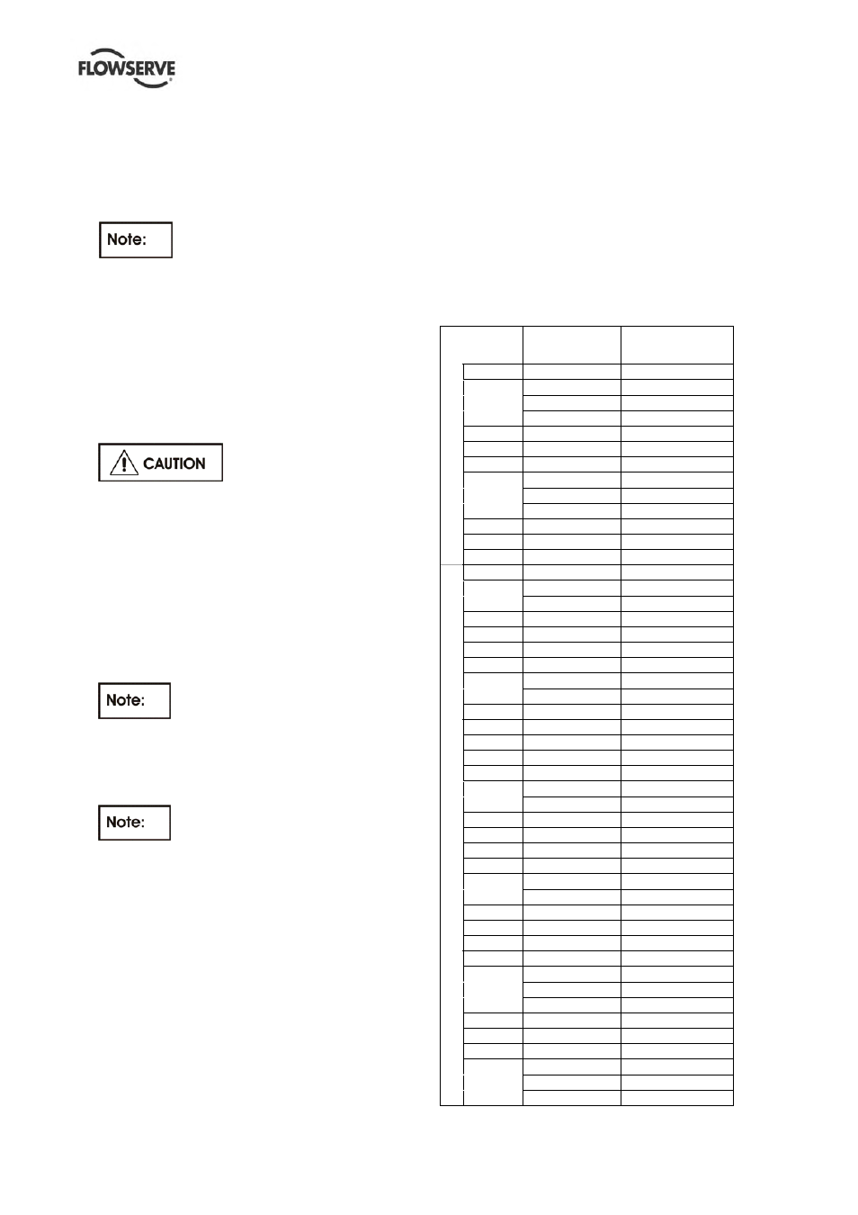
6.8.1 Gap at closed impeller – ERPN-M
The diametrical gap between wear rings [367]
and [433] in assembled condition is:
Pump size
Wear ring
diameter mm (in.)
Diametrical
clearances mm (in.)
25-125 78 (3.1)
0.3 (0.012)
25-160 78 (3.1)
0.3 (0.012)
25-200 78 (3.1)
0.3 (0.012)
32-125 78 (3.1)
0.3 (0.012)
32-160 78 (3.1)
0.3 (0.012)
32-200 78 (3.1)
0.3 (0.012)
40-125 90 (3.5)
0.3 (0.012)
40-160 90 (3.5)
0.3 (0.012)
40-200 105 (4.1)
0.3 (0.012)
50-125 95 (3.7)
0.3 (0.012)
50-160 105 (4.1)
0.3 (0.012)
50-200 105 (4.1)
0.3 (0.012)
FRAME 1
65-125 114 (4.5)
0.3 (0.012)
32-250 90 (3.5)
0.3 (0.012)
40-250 105 (4.1)
0.3 (0.012)
50-250 105 (4.1)
0.3 (0.012)
65-160 138 (5.4)
0.35 (0.014)
65-200 138 (5.4)
0.35 (0.014)
65-250 138 (5.4)
0.35 (0.014)
80-160 138 (5.4)
0.35 (0.014)
80-200 169 (6.7)
0.35 (0.014)
100-200 169 (6.7)
0.35 (0.014)
FRAME 2
125-204 176 (6.9)
0.25 (0.010)
40-315 105 (4.1)
0.3 (0.012)
50-315 124 (4.9)
0.35 (0.014)
65-315 138 (5.4)
0.35 (0.014)
80-250 138 (5.4)
0.35 (0.014)
80-315 169 (6.7)
0.35 (0.014)
80-404 169 (6.7)
0.35 (0.014)
100-250 169 (6.7)
0.35 (0.014)
100-404 169 (6.7)
0.35 (0.014)
125-254 179 (7.1)
0.35 (0.014)
125-319 184 (7.2)
0.35 (0.014)
125-404 184 (7.2)
0.35 (0.014)
150-250 225 (8.9)
0.4 (0.016)
150-254 225 (8.9)
0.4 (0.016)
150-319 225 (8.9)
0.4 (0.016)
FRAME 3
200-254 242 (9.5)
0.4 (0.016)
50-380 124 (4.9)
0.35 (0.014)
65-400 138 (5.4)
0.35 (0.014)
80-400 169 (6.7)
0.35 (0.014)
100-315 169 (6.7)
0.35 (0.014)
150-315 225 (8.9)
0.4 (0.016)
150-404 225 (8.9)
0.4 (0.016)
200-250 235 (9.3)
0.4 (0.016)
200-319 256 (10.1)
0.4 (0.016)
200-404 256 (10.1)
0.4 (0.016)
FRAME 4
250-319 300 (11.8)
0.4 (0.016)