0 auxiliaries 7.1 secondary seal, 2 changing of secondary seal, 3 seal and seal systems – Flowserve ERPN-M User Manual
Page 30
ERPN-M USER INSTRUCTIONS ENGLISH 02-08
Page 30 of 37
2) Heat up the inner race of the roller bearing [476]
and push it on the shaft [415].
3) Install both retaining rings [4771] into bearing
housing. Push line bearing [476] without inner
race into the bearing housing [470]. Mount radial
bearing cover [478] including O-ring [493] by
using hex screws [031].
4) Insert shaft [415] with already mounted bearings
into prepared bearing housing [470]. Mount thrust
bearing cover [479] including O-ring [493] by
using hex screws [031].
5) Put in the labyrinth type seal [4791] into thrust
bearing cover [479].
Take care that the oil return slot of
the bearing cover is at the bottom and one slot of
the labyrinth ring meets the oil return slot.
6) Check if the rotor can be turned by hand.
7) Turn complete unit by 180°, so that shaft end
shows downwards and bearing housing [470] with
thrust bearing cover [479] lies on the workbench.
8) Put gasket [495] into barrel [471] and mount line
bearing cover [478] by socket screws [021].
Do not forget to put shaft seal into line
bearing cover [478].
9) Put new O-ring [494] into groove of bearing
housing [470] and pull the pre-mounted barrel [471]
through the impeller shaft [415] over the bearing
housing [470] and bolt the two casings together by
studs [034] and hex nuts [035].
10) Now put key [423] into the keyway and driving
flange [465] inclusive outer rotor [M02] secured by
socket screws [045] on driving shaft [415] and fix it
with retaining ring for shaft [4651].
Pay attention that guard ring
[4711] is pressed in barrel [471] and the gasket
[398] is assembled.
11) Now lift complete pre-mounted outer rotor slowly
by crane on the pre-mounted inner rotor of pump
with the aid of cylindrical pins [044] which are
screwed into the pump casing [360].
The outer rotor [M02] of
magnetic coupling must not touch can, [M03]
otherwise the magnets will be destroyed.
Pay attention to hex screw [036] so
that they do not block assembly of pump. For
torques refer to section 6.5 Fastener torques.
12) Check whether you can turn rotor by hand. Fit the
„Constant Level“ oiler and fill oil into bearing
housing.
For correct oil level and adjustment
refer to section 5.2.1, Lubrication.
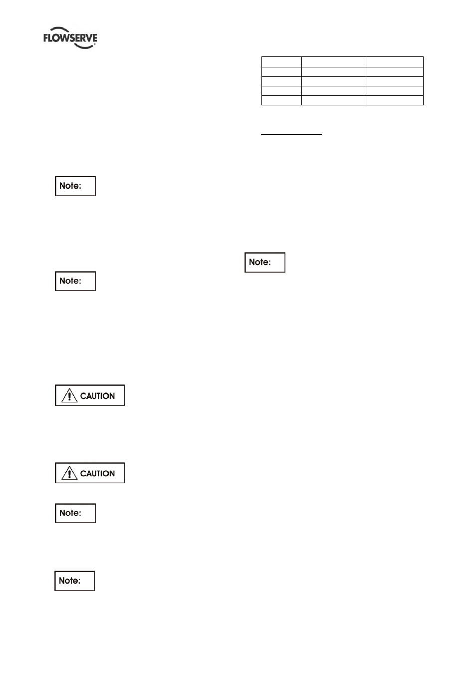
Frame
Thrust bearing
Line bearing
1
6306 – C3
NU 207
2
6306 – C3
NU 207
3
6309 – C3
NU 209
4
6309 – C3
NU 209
7.0 AUXILIARIES
7.1 Secondary Seal
The pump is equipped with a secondary containment
seal. This can be a non-contacting lip seal or a non-
contacting dry gas seal (refer to sectional drawing).
The purpose of this seal is to avoid leakage to
atmosphere in case of a failure of the magnetic
coupling.
During normal operation the barrel [471] is exposed
to atmospheric pressure, in case of failure of the
magnetic coupling the barrel will be pressurized and
non-contacting seal will close.
We strictly recommend to install a
pressure switch, which shut down the pump in case a
pressure is build up in the barrel. This avoids further
damage of the pump and the secondary seal seals
against static pressure only.
7.2 Changing of secondary seal
Refer to section 6.7.2, Dismantling of the outer rotor,
and section 6.9.2, Assembly of the outer rotor.
7.3 Seal and seal systems
7.3.1 Flushing plan no. 1S according to API 685
Flushing of magnetic coupling is performed according
to API 685 flushing plan no.1S. Thereby the pumped
medium is led to the magnetic coupling internally
from higher pressure side through a small hole in
casing cover [370].
Flushing medium circulates through magnetic
coupling and enters afterwards into pump casing, into
the space behind impeller, (low pressure).
Circulation is necessary for lubricating the bearings
and for eliminating heat caused by the eddy current
losses.
7.3.2 Flushing plan no. 11S according to API 685
Flushing of magnetic coupling is performed according
to API 685 flushing plan no.11S. Thereby the pumped
medium is led to magnetic coupling (connection „F“)
from pump discharge through an orifice.
Flushing medium circulates through magnetic
coupling and enters afterwards into pump casing, into
the space behind impeller, (low pressure).
Circulation is necessary for lubricating the bearings
and for eliminating heat caused by the eddy current
losses.