3 adjusting the foundation frame, 3 initial alignment, 1 thermal expansion – Flowserve LNGT User Manual
Page 17: 2 alignment methods
LNGT USER INSTRUCTIONS ENGLISH 00083107 02-08
Page 17 of 48
®
shrinking grout [for example Pagel V1 or
equivalent].
Leave the grout to cure according to the
grout manufacturer's instructions.
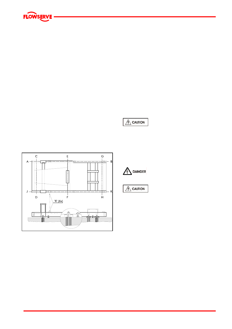
4.2.3 Adjusting the foundation frame
Use a calibrated machine levelling instrument
accurate to 0.02 mm/m
1
. Make sure to measure
in both directions by placing the levelling
instrument on the reference locations which have
been fitted on the foundation frame for this
purpose. If a shaft seal protector has been fitted,
it should be removed.
Adjust the foundation frame horizontally in A-
B direction to a degree of accuracy of 0.05
mm/m
1
using thin shims, see Figure 3.
Tighten the foundation nuts along the A-B
axis using a torque of ¼ of the maximum
allowable tightening torque [M
max
] for the
foundation bolt.
Adjust the foundation frame in C-D, E-F and
G-H directions to a degree of accuracy of
0.05 mm/m
1
using thin shims.
Tighten the foundation nuts using a torque of
¼ of the maximum allowable tightening
torque [M
max
] for the foundation bolt.
Check whether all foundation nuts are tight.
Align the electric motor to the centerline of
the pump using shims between the
supporting faces of the foundation frame and
the feet of the motor. The maximum
allowable deviation, both axially and radially,
should not exceed 0.05 mm and depends on
the coupling type.
Loosen all adjusting bolts and measure
whether the foundation frame is level in all
directions to a degree of accuracy of 0.05
mm/m
1
.
Check whether the position and level height
in the centerline of the suction and delivery
connections are correct. If not, adjust these
as described above.
Fill the outer edges of the foundation frame,
including shims,
completely with non-
shrinking grout [for example Pagel V1 or
equivalent]. Leave the grout to cure
according to manufacturer's instructions.
Check whether the nuts of the foundation
bolts are still tight and, where necessary,
retighten these to the correct torque [¼ M
max
].
Reassemble the shaft seal protection if this
has been removed to enable horizontal
alignment
If required, draw up a report of the entire
alignment procedure.
4.3 Initial alignment
4.3.1 Thermal expansion
The pump and motor will normally
have to be aligned at ambient temperature and
should be corrected to allow for thermal
expansion at operating temperature. In pump
installations involving high liquid temperatures,
the unit should be run at the actual operating
temperature, shut down and the alignment
checked immediately.
4.3.2 Alignment methods
Ensure pump and driver are
isolated electrically and the half couplings are
disconnected.
The alignment MUST be checked.
Although the pump will have been aligned at the
factory it is most likely that this alignment will
have been disturbed during transportation or
handling. If necessary, align the motor to the
pump, not the pump to the motor.
Horizontal pumps – LNGT
Alignment is achieved by adding or removing
shims under the motor feet and also moving the
motor horizontally as required. In some cases
where the alignment cannot be achieved it will be
necessary to move the pump before
recommencing the above procedure.
For couplings with narrow flanges use a dial
indicator as shown below to check both parallel
and angular alignment.