4 piping – Flowserve LNGT User Manual
Page 18
LNGT USER INSTRUCTIONS ENGLISH 00083107 02-08
Page 18 of 48
®
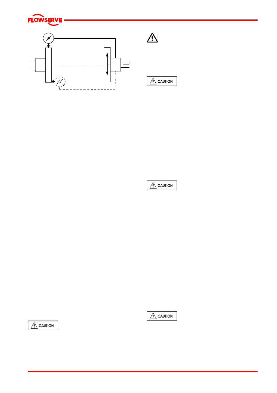
Parallel
Angular
Maximum permissible misalignment at working
temperature:
Parallel 0.1 mm [0.008 in.] TIR
Angular 0.05 mm [0.004 in.] TIR
When checking parallel alignment, the total
indicator read-out [TIR] shown is twice the value
of the actual shaft displacement.
Align in the vertical plane first, then horizontally by
moving motor. When performing final alignment,
check for soft-foot under the driver. A TIR indicator
placed on the coupling, reading in the vertical
direction, should not indicate more than 0.05 mm
[0.002 in.] movement when any driver foot fastener
is loosened.
While the pump is capable of operating with the
maximum misalignment shown above, maximum
pump reliability is obtained by near perfect
alignment of 0.05 to 0.10 mm [0.002 to 0.004 in.]
TIR parallel and
0.05 mm [0.002 in.] per 100 mm [4 in.] of coupling
flange diameter as TIR angular misalignment. This
covers the full series of couplings available.
Pumps with thick flanged non-spacer couplings
can be aligned by using a straight-edge across
the outside diameters of the coupling hubs and
measuring the gap between the machined faces
using feeler gauges, measuring wedge or
calipers.
When the electric motor has sleeve bearings it is
necessary to ensure that the motor is aligned to
run on its magnetic centerline.
Refer to the motor manual for details.
A button [screwed into one of the shaft ends] is
normally fitted between the motor and pump shaft
ends to fix the axial position.
If the motor does not run in its
magnetic centre the resultant additional axial
force may overload the pump thrust bearing.
Complete piping as below and see sections
4.7, Final shaft alignment check up to and
including section 5, Commissioning, start up,
operation and shutdown before connecting driver
and checking actual rotation.
4.4 Piping
Protective covers are fitted to the
pipe connections to prevent foreign bodies
entering during transportation and installation.
Ensure that these covers are removed from the
pump before connecting any pipes.
4.4.1 Suction and discharge pipe work
In order to minimize friction losses and hydraulic
noise in the pipe work it is good practice to
choose pipe work that is one or two sizes larger
than the pump suction and discharge. Typically
main pipe work velocities should not exceed 2
m/s [6 ft/sec] suction and 3 m/s [9 ft/sec] on the
discharge.
Take into account the available NPSH which
must be higher than the required NPSH of the
pump.
Never use the pump as a support
for piping.
Maximum forces and moments allowed on the
pump flanges vary with the pump size and type.
To minimize these forces and moments that may,
if excessive, cause misalignment, hot bearings,
worn couplings, vibration and the possible failure
of the pump casing, the following points should
be strictly followed:
• Prevent excessive external pipe load
• Never draw piping into place by applying
force to pump flange connections
• Do not mount expansion joints so that their
force, due to internal pressure, acts on the
pump flange. It is recommended that
expansion joints use threaded rod to limit any
forces of this type
The table in 4.4.3.1 and 4.4.3.2 summarizes the
maximum forces and moments allowed on LNGT
pump casings. Refer to Flowserve for other
configurations.
Ensure piping and fittings are
flushed before use.
.