5 seal assembly preparation, 6 seal assembly instructions – Flowserve ISC2 Single Pusher Repair User Manual
Page 4
4
5 Seal Assembly Preparation
Tools Needed:
• Sizes ≤ 2.750": 3/16", 1/8" hex key wrenches
• Sizes > 2.750": 1/8", 3/16" and/or 7/32" hex key wrenches
• Sizes ≤ 65 mm: 3 mm hex key wrench
• Sizes > 65 mm: 5 mm hex key wrench for standard bore
• Sizes > 65 mm: 6 mm hex key wrench for enlarged bore
• Silicone grease (included in repair kit)
• Ethyl alcohol and clean, lint-free towel for cleaning seal faces
• Needle nose pliers or tweezers
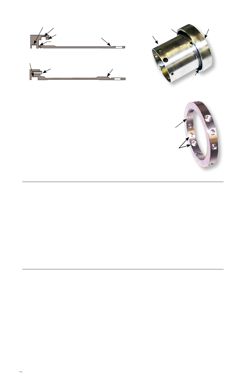
Figure 5
Figure 6
4.3 Drive Collar [58] see Figure 6.
A Threaded holes - Inspect for thread damage
and re-tap as necessary.
B ID bore roundness - No greater than 0.002 inch
(0.05 mm) TIR.
C Set screws - Replace cup-point and quarter-dog point
set screws with those
included with the repair kit.
Make sure the same threaded holes are used.
C
B
A
B
A
B
A
A
C
A
Figure 4b, sizes > 2.750 inch (70 mm)
Figure 4a, sizes ≤ 2.750 inch (70 mm)
B
6 Seal Assembly Instructions
Some assembly steps include blind fits of pins and drive flats. Mark the locations
of the pins or drive flats with a felt tip marker, or align the feature with another
visible feature on the seal to assist with assembly. All seal faces should be
cleaned with ethyl alcohol prior to placing the faces together at each respective
step in the assembly process.
6.1 Arrange O-rings by diametrical size. There are two sizes: quantity 3 of the
largest size [13], [13.1] and [76], and quantity 1 of the smallest size [19].
Prior to installing each O-ring at its respective step, lightly lubricate with
silicone grease, unless an alternative lubricant is specified, and stretch
slightly.
6.2 Place the sleeve assembly [1] on the work surface with the drive end (set
screw holes) positioned upward.
D
A
C