Flowserve ISC2 Single Pusher Repair User Manual
Page 7
7
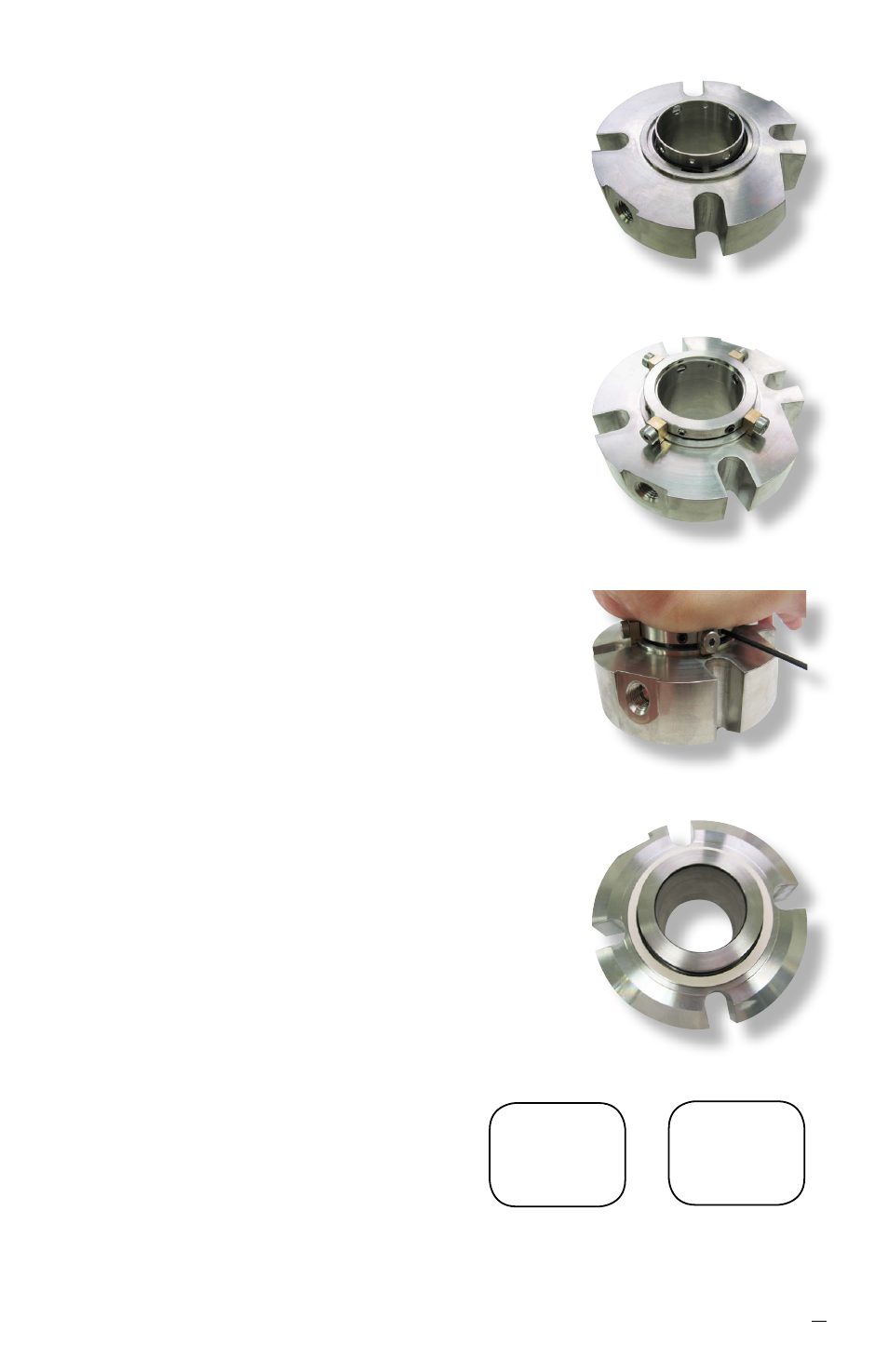
6.17 Perform a dry fit of the collar on the sleeve.
6.18 Install the drive collar [58] onto the sleeve
assembly [1]. The drive collar may need to be
rotated so that the set screws [57] line up with the
large holes and quarter-dog set screws [57.1] line
up with the two smaller holes.
Note: Some sizes > 2.750" do not utilize quarter-
dog set screws.
6.19 Install the setting devices and cap screws [103]
and [40] into the drive collar, engaging with the
gland [11]. See Figure 17.
Caution: Do not rotate the gland assembly
during installation. This may cause the springs
[16] installed in step 6.12 to buckle if the gland
assembly [11] is rotated with respect to the
stationary face support [100].
6.20 While compressing seal by pushing down on
gland assembly [11], tighten the quarter-dog set
screws [57.1] to engage into the two smaller holes
of the sleeve assembly [1]. If the seal does not
contain quarter-dog set screws then install the set
screws [57] into the sleeve [1]. See Figure 18.
Caution: Over tightening will cause distortion
of the sleeve assembly [1]. Check integrity of
the sleeve with a plug of the appropriate size to
ensure no distortion has occurred.
6.21 Install sleeve O-ring [19] into the inner diameter
groove of the sleeve assembly.
6.22 The cartridge seal assembly is now ready for
testing.
6.23 Adhere the gland gasket [18] to the gland gasket
surface with a spray adhesive such as 3M Super
77
®
. See Figure 19.
6.24 Permanently mark the seal type ISC2-PX or
ISC2-XP, seal size and gland ring
material clearly on the gland surface.
See Figure 1 for placement location.
Figure 16
Figure 17
Figure 18
ISC2-PX
M060
316 SS
Example
inch
marking
ISC2-PX
1.875
316 SS
Example
metric
marking
Figure 19