Flowserve ISC2 Single Pusher Repair User Manual
Page 6
6
6.8 Select O-ring [13]. Lightly lubricate the O-ring using silicone grease. Install
the O-ring onto the stationary face [14]. See Figure 11.
Figure 12
Figure 13
Figure 15
6.9 Select the square-headed pins [5] and dab
silicone grease on the tip of each pin before
inserting to assist keeping pins in place. Install
the long end of the pins into the stationary face
support [100]. Tweezers or needle nose pliers
may assist installation of the pins. See Figure 12.
6.10 Select the stationary face [14] and install it onto
stationary face support [100], the square-headed
pins must line up with the slots in the stationary
face [14]. Silicone grease may be applied to the
O-ring bore in the stationary face support [100].
6.11 Clean the sealing face of the stationary face [14]
to remove dirt, dust, fingerprints or any other
residue using alcohol on a clean cloth or tissue.
6.12 Install springs [16] into the holes in the stationary
face support [100]. Silicone grease should be
used to hold the springs in the spring holes. See
Figure 13.
6.13 Install the stationary face assembly down onto
the sleeve assembly as shown in Figure 14.
6.14 Lightly lubricate the area where the O-ring [13]
will ride on the stationary face support [100] with
silicone grease. See Figures 14, area A.
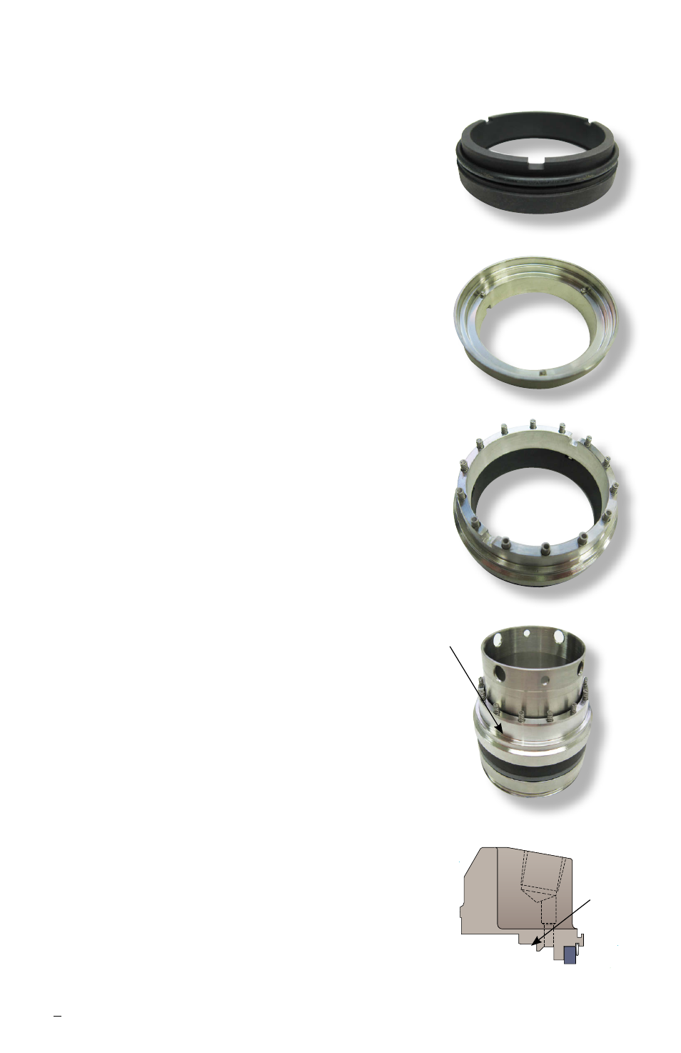
Lightly lubricate the area where the O-ring [13]
will ride in the gland [11] with silicone grease.
See Figure 15, area B. Install the dynamic
O-ring [13.1] into the gland [11].
6.15 Install the gland assembly [11] onto the sleeve
assembly. See Figure 16. During the installation,
ensure that the drive pins in the gland line up
with the slots in the stationary face support [100].
Caution: Do not rotate the gland assembly
during installation.This may cause the springs
[16] to buckle. Verify the pins are aligned with the
slots by exercising the gland.
6.16 Thread set screws and quarter-dog set screws
in proper, equally spaced locations in drive collar
[58].
Note: Some sizes > 2.750 inch (70 mm)
do not utilize quarter-dog set screws.
Figure 11
Figure 14
A
B