Flowserve Q Series BW Seals User Manual
Page 5
5
4.3 Verify seal setting (SS) reference dimension on the seal drawing. This is the
dimension from the seal chamber face to a machined step or locator on the shaft.
See Figure 3.
4.4 If shaft sleeve has no locating shoulder, blue sleeve and scribe line for location of
spring holder as shown on seal assembly drawing.
4.5 Slide rotating assembly onto shaft sleeve, locating in accordance with the seal
assembly drawing. Use caution not to dislodge rotating face gasket.
4.6 Tighten seal assembly set screws to shaft sleeve ensuring seal assembly is
retained at proper seal setting location as noted on seal assembly drawing.
4.7 O-ring mounted Stationary Face
4.7.1 Assemble seat gasket to stationary face (lubricate gasket with silicone base
grease only) and install in gland.
Caution:
If anti-rotation pin is used make sure stationary face is properly seated.
Do not get grease on running face.
4.7.2 Install gland gasket, use silicon grease if necessary to retain gasket.
4.8 Clamped Stationary Face
4.8.1 Install flat gasket into inner gland.
4.8.2 Install stationary face into gland.
4.8.3 Install second flat gasket to stationary face.
Note:
If two gasket materials are supplied, install PTFE gasket at this location.
Use silicone grease to retain gasket if necessary.
Do not get grease on running face.
4.9 Using lint free tissue, clean stationary and rotating face mating surfaces. Alcohol
or acetone can be used as a cleaning agent to assure clean, film free, dry faces. Any
other materials may cause premature seal failure.
Caution:
Consult material safety data sheet for proper handling of alcohol or acetone.
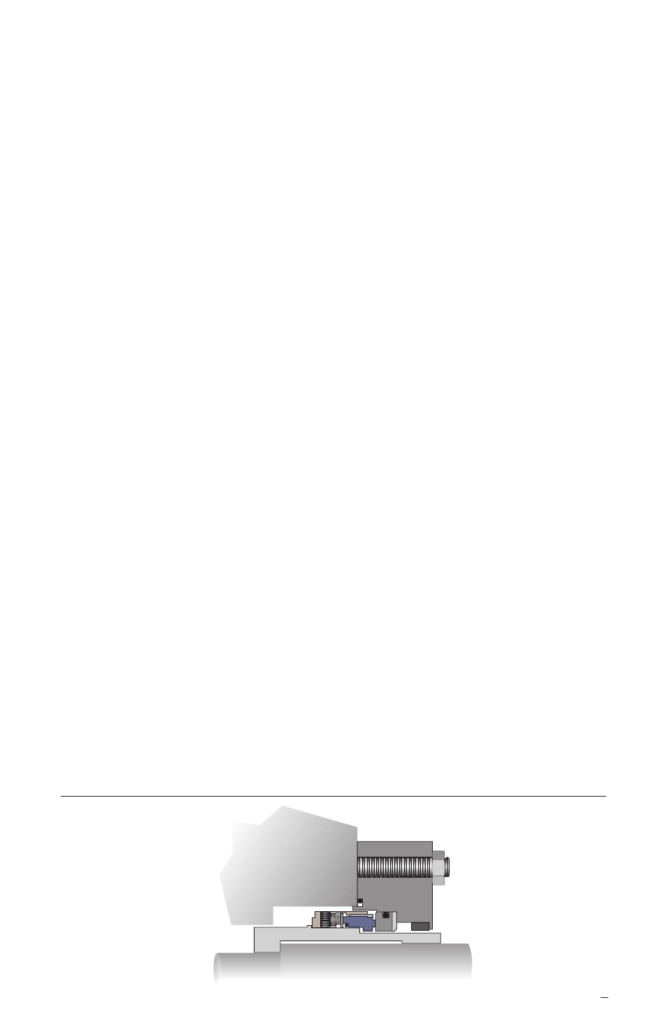
4.10 Assemble gland to seal chamber face. See Figure 4.
Caution:
During gland assembly over shaft and sleeve, be sure stationary face is not
damaged. Secure bolts attaching gland to housing.
Note:
Even torque is required on all gland bolts to assure proper seal operation.
Tighten gland stud nuts evenly, cross stagger the adjustment of the nuts. Follow the
equipment manufacturer’s recommendation for gland stud nut torque. In the absence
of recommendations, gland stud nuts should only be torqued to establish a leak tight
seal at the gasket. Proper land bolt adjustment is especially important with clamp
style inserts where torque may damage the insert. In this case, gland stud nuts
should be torqued to a maximum of 13.5 N-m (10 ft-lbs).
Installed Seal Assembly on Hook Sleeve Figure 4