5 cartridge mount – Flowserve Q Series BW Seals User Manual
Page 6
6
5 Cartridge Mount
5.1 For proper seal installation you must have current seal assembly drawing
for your application.
5.2 Inspect pump shaft. Clean and remove any burrs, nicks, scratches, etc.,
which could cause damage to gaskets when installing cartridge seal.
5.3 Carefully install the seal onto the shaft and locate against the face of the seal
chamber. Take care not to impact the seal cartridge as damage to internal
components can occur.
5.4 Orient ports on the seal cartridge as shown on the seal assembly drawing.
5.5 Evenly torque gland bolts/nuts to prevent uneven gland pressure against the
seal chamber.
5.6 Adjust bearings, coupling, and impeller so that the shaft is in its final operating position.
5.7 Determine the type of setting device used by the seal design and follow the
appropriate instructions.
Type 1 - none
Type 2 - setting plates
Type 3 - setting blocks
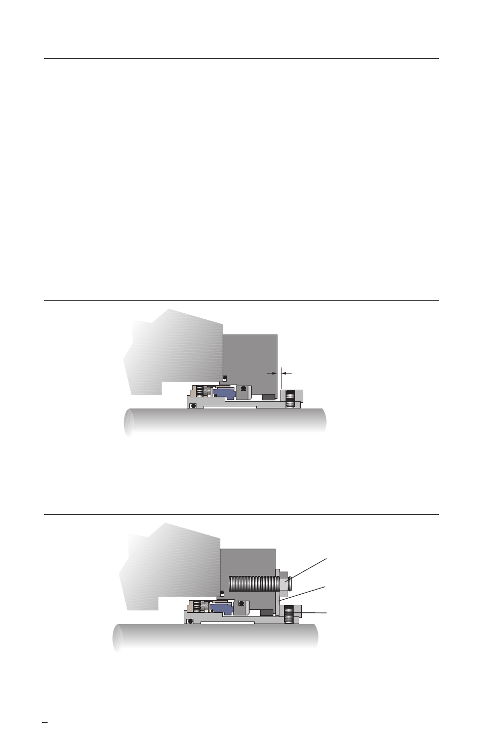
Type 1 (none)
Figure 5
• Determine proper seal setting (SS) gap specified on seal assembly drawing.
• Adjust sleeve drive collar position relative to gland to establish proper gap.
• Tighten drive collar set screws.
Type 2 (setting plates)
Figure 6
• Tighten drive collar set screws to shaft.
• Loosen setting plate attachment bolts and rotate or slide setting plates clear
of drive collar.
• Retighten setting plate attachment bolts.
Setting Plate Bolt
Setting Plate
Set Screws
SS Gap
(from assembly drawing)