Figure 2, Figure 3 – Flowserve Uniseal Series BW Seals User Manual
Page 3
3
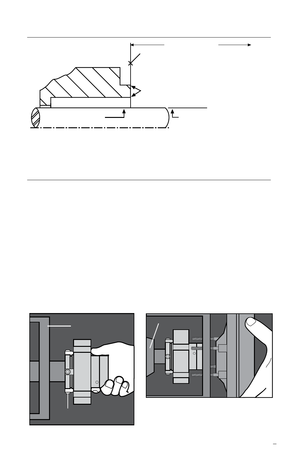
Seal Chamber Requirements
Figure 1
2
Uniseal Installation
Note: No seal setting measurements
are needed to install the seal. Instructions
are for end-suction back pull-out pumps. Modification of these procedures may be
required for other style pumps. Consult Flowserve for installation support.
2.1 Lubricate the shaft or pump sleeve lightly with silicone lubricant unless
otherwise specified.
2.2 Tighten the setting device cap screws to ensure they are tight before
installation.
2.3 Slide the Uniseal cartridge onto the shaft or pump sleeve with the setting
devices toward the bearing housing. See Figure 2.
2.4 Install the seal chamber and bolt it in place on the bearing frame.
See Figure 3.
2.5 Position the Uniseal with the gland tight against the seal chamber.
To first obstruction
Face of seal housing to be square to the axis
of the shaft to within 0.013 mm per millimeter
(0.0005 inches) of seal chamber bore FIM and
have a √1.6
μ
m (63
μ
inch) R finish or better
a
Gland pilot can be at either of these
register locations, concentric to within
0.13 mm (0.005 inch) FIM of shaft or sleeve OD
Seal housing bore to have √3.2 μm
(125 μinch) R finish or better
Sleeve or shaft finish to be
0.8 μm (32 μinch) R or better
a
a
Shaft or sleeve OD
+0.000 mm (+0.000 inch)
-0.050 mm (-0.002 inch) ANSI
+0.000 mm (+0.000 inch) API 610/682
-0.025 mm (-0.001 inch) DIN/ISO
• Bearings must be in good condition
• Maximum lateral or axial movement of shaft (end play) = 0.25 mm (0.010 inch) FIM
• Maximum shaft runout at face of seal housing = 0.05 mm (0.002 inch) FIM
• Maximum dynamic shaft deflection at seal housing = 0.05 mm (0.002 inch) FIM
Figure 2
Setting Device
Bearing Frame
Seal
Chamber
Figure 3
Bearing Housing