7gland gasket installation – Flowserve PSS II User Manual
Page 10
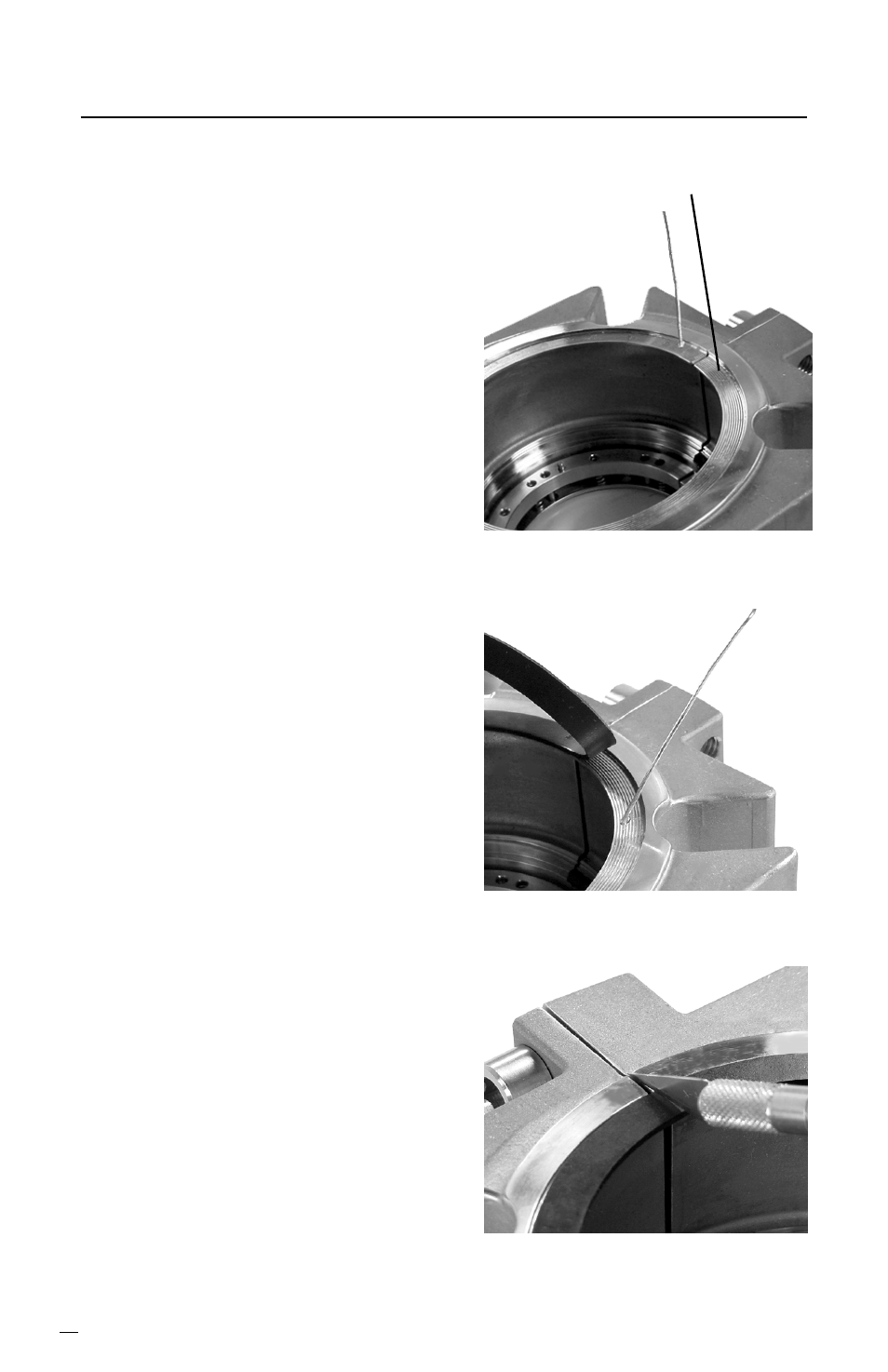
Figure 24
10
Figure 22
7
Gland Gasket Installation
7.1
The gland gasket should be
installed with one dot of adhesive
every 0.50 inch (12.7 mm) with
an extra dot of adhesive 0.25
inch (6.35 mm) both sides of the
gland joint.
7.2
Coat the cap screws with anti-
seize and assemble the gland
halves. Tighten the cap screws
until the gland joints are metal to
metal.
7.3
Wipe the gland gasket groove
clean with alcohol.
Caution: Consult material safety data
sheets for proper handling of alcohol.
7.4
Apply one dot of adhesive to the
gland gasket groove about 0.25
inch (6.35 mm) from a gland joint.
See Figure 22.
7.5
Center the gland gasket in the
gasket groove and hold it in
place for 10 seconds.
7.6
Apply another dot of adhesive
0.50 inch (12.7 mm) from the first
dot and hold the gland gasket at
that dot for 10 seconds. Repeat
this step every 0.50 inch (12.7
mm) around the groove
circumference. See Figure 23.
7.7
Loosen the cap screws about 1/2
turn. Spread the gland joints and
cut the gland gasket at these
locations. See Figure 24.
Face Gasket Groove
Figure 23