2dual gas barrier seal installation – Flowserve Dual Gas Barrier Seals User Manual
Page 3
3
1.6 Check equipment dimensions. They must agree with the
dimensions shown in Figure 1 and the assembly drawing
supplied with the seal. Critical dimensions include shaft or
sleeve OD and the minimum distance to the first obstruction.
1.7 Check gland bolting to ensure that bolt diameter and bolt
circle conform to the dimensions shown in the assembly drawing.
1.8 Check seal chamber stud length to ensure that they conform
to the dimensions shown in the assembly drawing. Assembly may
require longer studs or use of bolts or cap screws if existing studs
are not long enough.
1.9 Check rotation direction of the equipment. Uni-directional seal
designs must be operated only in the direction shown on the
seal gland.
1.10 Handle the seal with care, it is manufactured to precise
tolerances. The sealing faces of the rotors and stators are
specially finished. Keep the seal faces perfectly clean at all
times. Oil, silicone lubrication, or type of grease should not be
applied to these seal faces.
2
Dual Gas Barrier Seal Installation
Tools needed:
Provided
• Krytox* lubricant for
sleeve O-rings
Not provided
• Open end wrench for
gland nuts
• Allen wrenches for
setting devices and set
screws
• Allen wrenches for
gland cap screws if they
are required in place of
gland nuts or bolts
*Krytox a Registered Trademark of E.I.DuPont
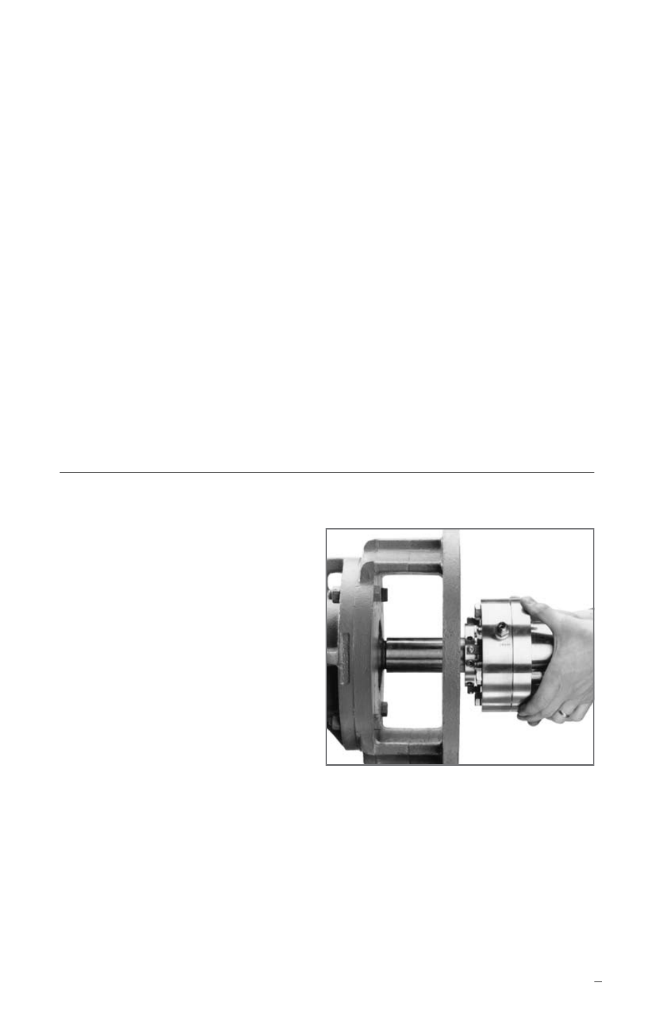
Install Seal Cartridge
Figure 2
2.1 Lubricate the shaft or sleeve OD lightly with Krytox lubricant
provided. If bolts or cap screws are required in place of the seal
chamber studs, insert them through the gland bolt holes before
sliding the assembly onto the shaft. Slide the complete seal
cartridge onto the shaft, Figure 2, with the end with the setting
devices toward the bearing housing.
Note: Check for rotation direction requirements on the seal gland or
assembly drawing before continuing.