Plan 74 for dual gas barrier seal – Flowserve Dual Gas Barrier Seals User Manual
Page 6
6
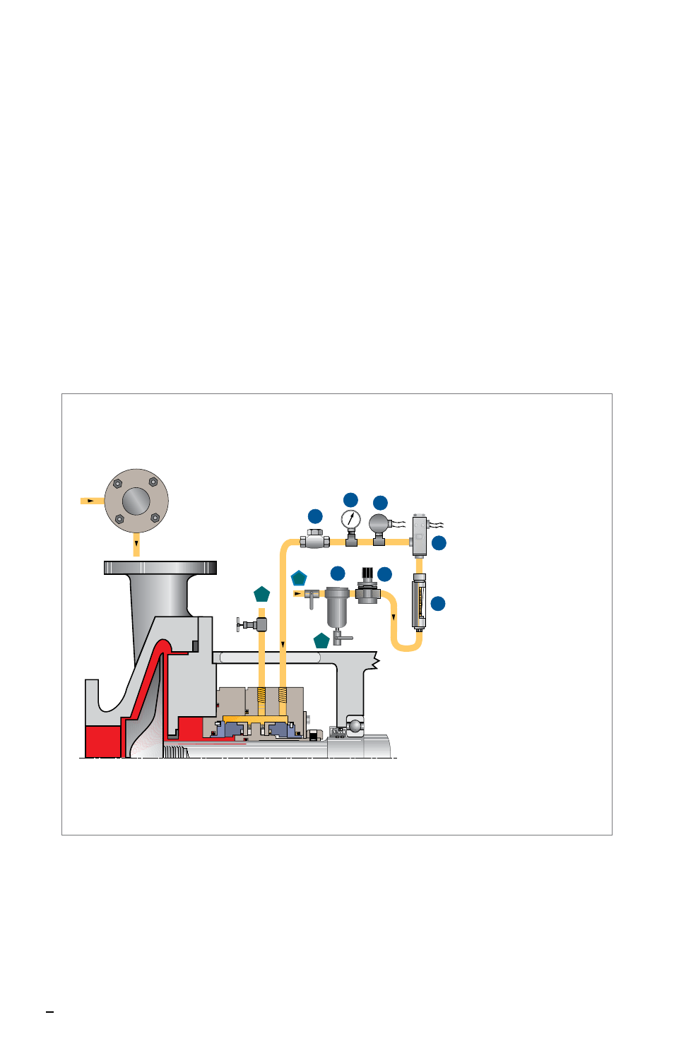
3.2 Connect gas barrier Plan 74 shown in Figure 8 to the gas
barrier inlet port (refer to Figure 5). The pressure gage and
regulator are required to set the barrier gas pressure 2 to 4 bar
(25 to 50 psig) higher than that of the product being sealed
(seal chamber pressure).
Note: It is important that the pressure gage and the low pressure alarm
be installed close to the gas barrier inlet port for accurate values.
An optional control panel that incorporates all the equipment in a Plan 74
for a Dual Gas Barrier Seal is available from Flowserve.
3.3 Plug the gas barrier outlet port, (refer to Figure 5), or connect to a
block valve.
Plan 74 for Dual Gas Barrier Seal
Figure 8
seal
end view
gas barrier outlet
gas
barrier
inlet
1
3
2
C
D
A
B
E
F
G
1 - gas barrier outlet, normally closed
2 - gas barrier inlet, normally open
3 - filter drain, normally closed
A - coalescing filter
B - regulator
C - flow indicator
D - flow switch (high)
E - pressure switch (low)
F - pressure indicator
G - check valve