Flowserve Trunnball User Manual
Naf-trunnball ball valves
NAF-Trunnball ball valves
Maintenance and installation instructions
List of spare parts
Fi 41.66(2)GB
08.09
Contents
SAFETY
General
1
Lifting
2
Receiving inspection
3
Installation
4
Flange gaskets
5
Starting up
6
Ordering of spare parts
7
Maintenance
8
To remove the valve from the pipework
8.1
To inspect and replace the ball and seatrings
8.2
Valves with seatrings in PTFE
8.3
Valves with chromium-plated ball and
seatrings in alloy 6
8.4
Valves with ball and seatring in alloy 6
8.5
To change the stem bearing and packing box type
8.6
PSDCL, i.e type 898_EF-XXXX-BABADA
To change the upper stem sealing with o-rings
8.7
i.e. type 898_95-XXXX.
To change the stem bearing and sealing i.e. type
8.8
898_95-XXXX.
Mounting the actuator to the valve
8.9
SAFETY
- Assess all the risks to eliminate the risk of personal
injury and material damage. Read these instructions
thoroughly!
- Always use the necessary protective equipment
and comply with applicable safety directives when
working with hazardous or hot/cold medium.
- Never operate a valve without fi rst ensuring that there
is no risk of crush injuries. The risk is highest with
automatic valves.
- Take necessary safety precautions to prevent
unintentional manoeuvre - i.e to atmosphere.
- Never dismantle a valve or part of a valve without
ensuring that the line is free of pressure and any
content.
- Ball valves must always be dismantled in semi-open
position to avoid trapping pressure and medium.
- Always check that the valve type and material is
suitable for its intended use. This applies especially to
highly oxidising and corrosive medium. Observe also
the risk of erosion and explosion as well as decaying
medium. If in doubt, always request a written
recommendation from NAF AB.
1. General
This instruction is valid for NAF-Trunnball ball valves in
accordance with catalogue sheet Fk 41.66 GB.
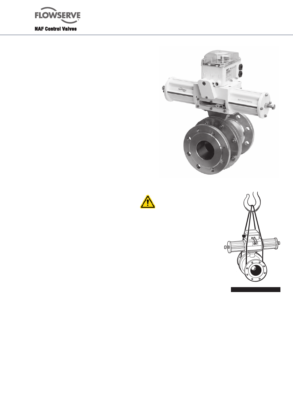
2. Lifting
All lifting must be made in
the valve itself and not in the
actuator. The joint between
the valve and the actuator
is designed principally for
carrying the operating torque
and the deadweight of the
actuator (see Fig. 1).
Fig. 1. Lifting of the valve
3. Receiving inspection
All valves leaving our works are inspected and tested
in accordance with the relevant requirements or in
accordance with the special conditions specifi ed by the
customer. Valves equipped with actuators are subject to
functional testing and are adjusted in such a manner that
every unit is completely ready for direct installation in
the pipework. However, in view of damage that may have
occurred during transport, it is advisable that receiving
inspection is performed, if possible.
We would suggest the following inspection procedure:
-
Check that the valve delivered is correct in
terms of type, size, equipment, etc.
-
Examine the valve, actuator and valve positioner
regarding possible damages.