Installation, Flange gaskets, Starting up – Flowserve Trunnball User Manual
Page 2: List of materials and spare parts
4. Installation
Before installing the valve, ensure that the pipework is
free from impurities, that the pipe ends between which
the valve is to be installed are parallel and are correctly
aligned, and that the distance between the pipe ends
corresponds to the valve length, including gaskets. The
valve must not be used for drawing together or aligning
incorrectly run pipes as this will cause needless loads on
the valve and pipe which may lead to diffi cult damages
during operation. See Fig. 2.
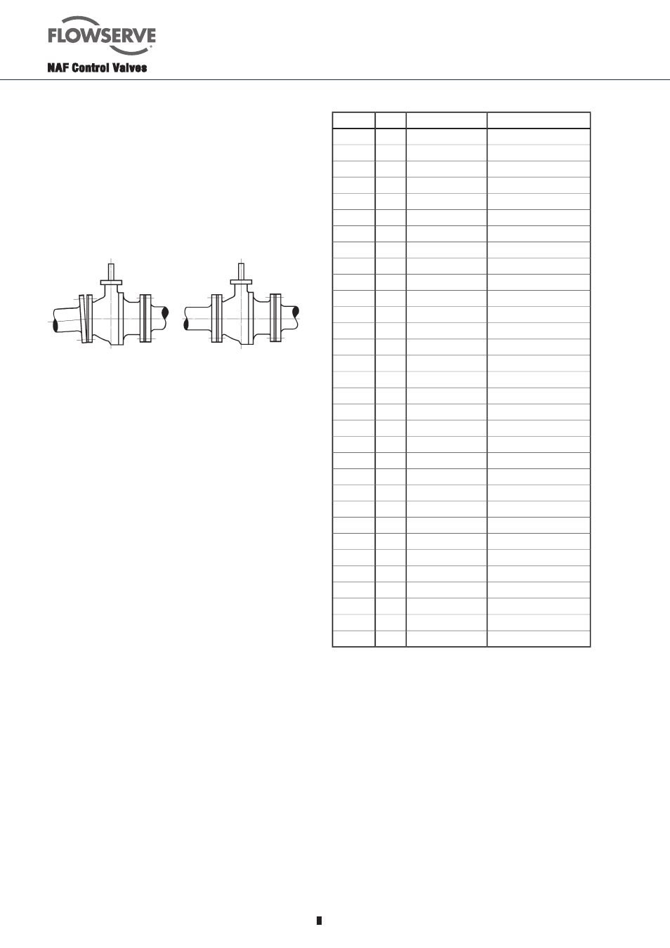
Wrong installation
Correct installation
Fig. 2. Ensure that the pipe ends align and have the
correct distance
NAF-Trunnball valves can be installed in any position
and with optional fl ow direction.
However, we recommend that, if installed in a horizontal
run of pipe, the valve should be mounted with the stem
pointing vertically upwards. If the valve is installed in a
vertical run of pipe, the body half (2) according to fi g. 3
should be at the top to enable the ball and the seat ring to
be replaced without the need for removing the valve from
the pipework.
The pipes should be supported on each side of the
valve, in order to relieve the valve of loads and avoid
vibrations.
Locate the valve so that it will be easily accessible for
inspection and service, particularly if the valve is equipped
with an actuator and a valve positioner.
5. Flange Gaskets
Gaskets with sizes according to ANSI B16.5 1988, Table
E1 Figure E2, SS 359 or DIN 2690 are recommended.
6. Starting up
Before starting up, fl ush the pipework - with all valves
in the open position - so that any impurities that may
damage the sealing surfaces of the valve and impede its
operation will be fl ushed away.
See also Fi 41.82 - Instruction Manual for NAF valve
positioner giving useful hints for starting up.
7. List of Materials and Spare Parts
Item No.
Qty.
Part
Material
1
1
Body
EN 1.4408/CF8M
2
1
Body
EN 1.4408/CF8M
3
1
Ball hard chrome
EN 1.4408/CF8M/Hcr
4
2
Seat ring
Alloy 6
5
1
Stem, assembly
EN 1.4460
6
1
Circlip
Spring steel
7
1
Backing ring
PTFE
8
1
Upper lid
EN 1.4436
9
4
Screw
A4
11
1
Packing box
PTFE/PTFE+25%C
12
1
Bushing
PTFE+1.4401
13
1
Anti-friction washer
EN 1.4436
14
1
Sealing ring
PTFE
15
10
Screw
A4-80
16
12
Nut
A4
17
2
Screw
A4-80
18
2
Key
A4
19
1
Ball
EN 1.4408/CF8M
20
1
Ball
Alloy 6
21
2
Seatring
EN 1.4436/PTFE+25%C
22
1
Bearing
PTFE+1.4401
23
2
Trunnion plate
EN 1.4470
24
2
Spring
ASTM A316
25
2
Sealing ring
PTFE+15%Graphite
26
1
O-ring
FPM
28
1
Spring
ASTM A316
29
1
Supporting ring
Spring steel
30
1
Washer
A4
31
1
Supporting ring
PTFE
32
2
O-ring
EPDM
33
2
Bushing
PTFE reinforced carbon
34
1
Sliding washer
PTFE reinforced carbon