Maintenance – Flowserve Trunnball User Manual
Page 5
5
3. Shut off all compressed air connections and
isolate all electrical connections to the actuator.
4. Disconnect all compressed air lines and electric
cables connected to the actuator.
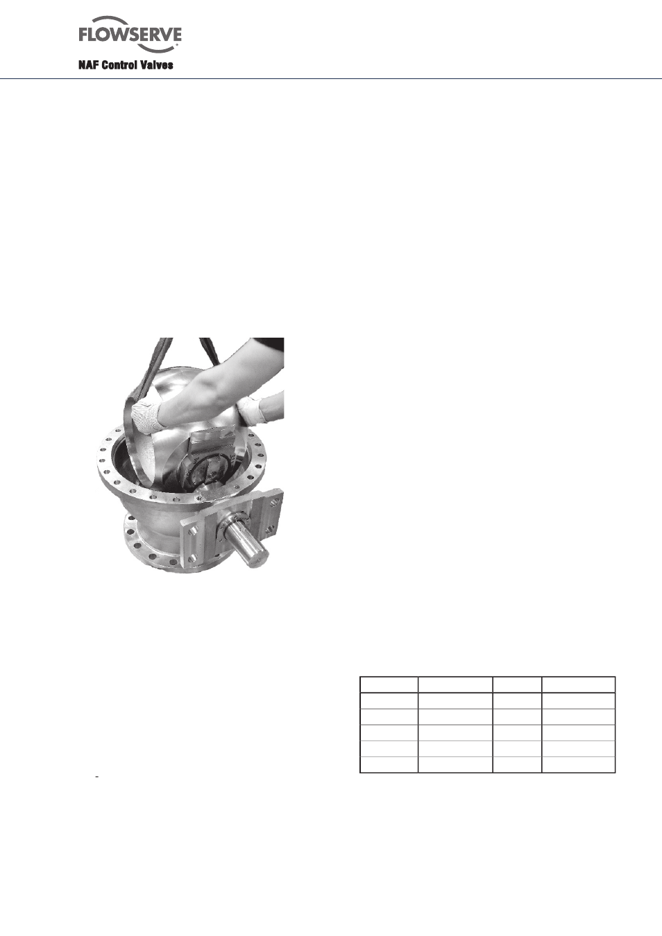
5. Loosen the fl ange joint between the valve and
the pipework. Then lift out the valve. Don’t use
the actuator for lifting. Apply all lifting forces to
the valve itself and not to the actuator - Fig. 1.
N.B. In certain applications, the pipe can be discon-
nected from one side of the valve, and the body
half (2) - Fig. 3 - can be removed, without the
need for removing the whole valve from the
pipework.
6. Mark the relative positions of the body halves
by centre-punching before the dismounting,
since the pattern of the holes drilled in the valve
fl ange and pipe fl ange may vary.
Fig. 4. Lifting the ball with the valve in closed posi-
tion - here with the valve on a work bench.
It can also be done with mounted actuator
and the body (1) mounted in the pipework.
8. Maintenance
Many valves are installed in such locations that their
performance is of decisive importance to the entire
process. Such valves should be inspected regularly
and any faults should immediately be corrected.
8.1 To remove the valve from the pipework
No special tools are needed for the inspection and
maintenance.
1. Ensure that the recommended spare parts and
gaskets for the pipe fl anges are available.
2. Close the valve.
Before dismounting the valve, make certain that
it is completely empty. Operate the valve several
times between the open and closed positions to
ensure that the space between the valve body and
ball is not under pressure.
Caution! The liquid in the valve may be harmful.
8.2 To inspect and replace the ball and seatrings
1. The actuator does not need to be removed for
replacing the seatring and ball.
2. Operate the valve to make certain that it is
completely empty. Close the valve.
3. Remove the bodyhalf (2).
4. Remove the ball and the trunnion plates - easy to
do when the valve is in closed position.
5. Remove the trunnion plates and the metaloplast
bearing from the bearing journal of the ball.
6. Carefully inspect the ball and the seatrings.
7. Clean all parts carefully. First use hot water and then,
if necessary, some degreasing compound. Do not
scrape any machined surfaces with hard tools.
8.3 Valves with seatrings in PTFE
1. To ensure good tightness of the valve, change the
seatrings, wave springs and sealings if they are worn
or damaged.
2. Mount the wave spring and sealing ring (pos 24 and
25) behind the seatring (pos 20).
3. Inspect the ball. Minor damage to the sealing surface
can be removed by polishing with fi ne emery cloth. If
the ball has major damages, it must be replaced to
ensure satisfactory tightness.
4. Change sealing ring (14) between the two body-
halves.
5. Change the metaloplast bearing in the trunnion plates.
6. Mount the bearing plates on the bearing journal of the
ball.
7. Coat the ball with Molycote U. If the valve is intended
for service in an oxygen system, the ball can be coa-
ted with silicone grease, which is approved for oxygen
applications.
8. Lubricate all stainless steel bolts with suitable grease,
i.e. Crane Packings’s Thread-Grade or Gleitmo 600.
9. Mount the ball and the bearing cage in the bodyhalf
(1) and then the upper bodyhalf (2). Make sure that
the centrepunch marks made according to section 8.1
item 6 are lined up. Tighten the bolted joint of the two
bodyhalves alternately in several stages and tighten
them fi nally as per the table below.
10. Torque for tightning of the bolted joint:
11. Operate the valve between closed and open positions.
12. If possible, pressure test the valve with water to check
its tightness - Fig. 5. Make sure that the cavities of the
valve are properly fi lled with water before the pressure
testing. The valve should be pressure tested as follows:
Open valve: PN x 1,5
Closed valve: Max dp x 1,1
Bolt
Torque NM
Bolt
Torque Nm
M12
76
UNC 1/2”
89
M16
187
UNC 5/8”
175
M20
364
UNC 3/4”
308
M24
629
UNC 7/8”
493
UNC 1”
737