Flowserve Trunnball User Manual
Page 6
8.4 Valves with chromium-plated ball and seatrings
in alloy 6
1. Check the sealing surfaces of the seatrings.
A groove on the inside of the ring facilitates with-
drawal. Minor damage to the rings can be polished
with fi ne emery cloth. Check the rings on a face
plate to ensure that they are perfectly fl at. Do
not lap the rings and the chromium-plated ball
together. Change the rings if they are severely
damaged.
2. Inspect the sealing surface of the ball. Minor
damage may be polished with fi ne emery cloth.
If the existing ball must be used for a further
period of time, remove all sharp edges, dents and
irregularities with a fi ne fi le or emery cloth. Check
the circularity of the ball. The tolerance is 0.04 mm.
If the ball is seriously damaged, it must be
replaced.
3. Mount the wave spring and the sealing ring (24
and 25) behind the seatring.
4. Change the sealing ring (14) between the
bodyhalves.
5. Lubricate the ball with a suitable grease, such as
Molykote U.
6. Continue assembling the valve as described in
section 8.3 item 8-12.
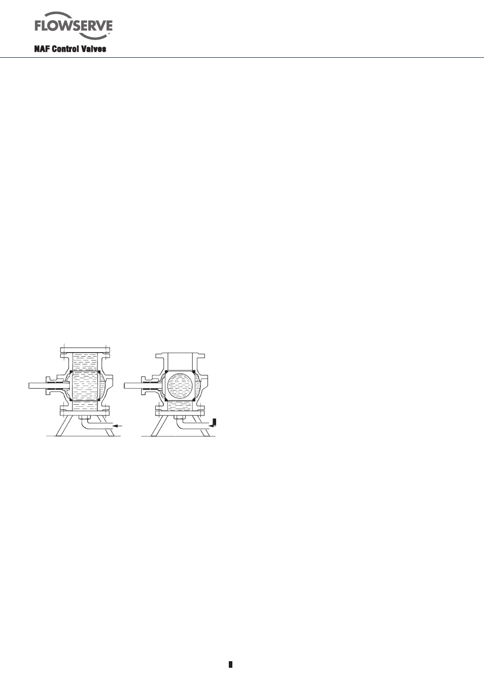
Valve open
Valve closed
Sealing fl ange
Water
Fig. 5. Pressure test of the valve with water
8.6
To change the stem bearing and sealing on
valves with packing box type PSDCL
(DN150-DN400) i.e. type
8982EF-XXXX-BABADA
1.
Dismount the actuator. Remove the screws that
from the underside of the mounting plate of the
valve keeps the actuator in place.
2.
Lift off the actuator from the valve. Remove the
keys.
3.
Dismount thte valve according to section 8.2.
4.
Remove the circlip (6), loosen the screws (9)
and remove the upper lid (8). Note! The upper
lid is prespringloaded.
5.
Remove the springs (28).
6.
Press the stem down into the body and remove
it.
7.
Pick up the anti-friction washer (13), supporting
ring (7), o-ring (26) and packing box (11).
8.
Dismount the bushing (12) by pressing it into
the body.
9.
Mount a new bushing (12) by pressing it up
through the body.
10.
Lubricate a new packing box (11) with silicone
grease before you press it down into the body.
Note that the broadest of the 5 rings should be
on top, see fi g 3 on page 3.
11.
Mount the stem by pressing if from the inside of
the body and out.
12.
Mount the supporting ring (7) in the anti-friction
washer (13), lubricate a new o-ring (26) with
silicone grease and mount it in the anti-friction
washer. Mount the anti-friction washer with the
o-ring downwards against the valve.
13.
Mount the remaining parts in reverse order from
item 5 to 1.
8.5 Valves with ball and seatrings in alloy 6.
1. The instructions for these valves are the same as
those in section 8.4 above.
2. If the sealing surfaces are damaged, we recom-
mend that the valve is returned to NAF for repair.
This applies especially if the ball must be ground
before lapping. Assemble the valve before dispat-
ching it to NAF.
3. The ball and seat rings can be temporarily renova-
ted by lapping them together. This can be done
manually with a compound with grit size 200. Take
great care to ensure that the ball and seat rings do
not become oval.
4. Balls in alloy 6 must be carefully cleaned and
lubricated before they are mounted. Use a suitable
solvent for cleaning. Then lubricate the ball with
silicone grease, such as Molykote Dow Corning
FS3452. The coat of grease must be very thin.
Then polish the ball with chamois leather or a
piece of soft cloth.
Water