0 disassembly – Flowserve Swing Check Valves 2.5-24 User Manual
Page 16
Swing Check Valves FCD ADENIM0013-00
15
5.0
DISASSEMBLY
(Continued)
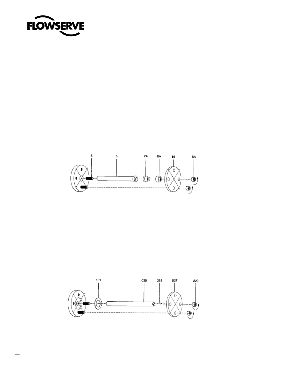
5.1.2.1.2 Pressure Seal Cover (Fig 12)
In this design, the hinge pin cover (10) holds a metal gasket (6A) against the hinge
pin bonnet (2A) by studs threaded into the body. As with the pipe plug design, in
small valves the bonnet may be an integral part of the hinge pin (5). To remove the
cover, unthread the nuts (8A) off the studs (8). The cover can then be removed. The
gasket and bonnet are most easily removed as one unit. The bonnet is provided
with a tapped hole in the end. If the hinge pin cover has not been disassembled for
a long period of time the gasket and bonnet may stick in the body. Prior to
attempting removal, lubricate the area well with penetrating oil. Although the hole in
the bonnet is intended for an eye bolt, if the bonnet is extremely tight a slide
hammer may be attached to the bonnet to free it. In withdrawing the bonnet/gasket it
is important to pull on the assembly squarely. If the bonnet/gasket becomes cocked,
removal can be quite difficult. Once the bonnet and gasket are removed, the hinge
pin can be withdrawn.
5.1.2.1.3 Blind Flange Cover (Fig 13)
In this design the cover (037) is held against a spiral wound gasket (101) by nuts on
studs threaded into the body. The cover can be removed after the cover nuts (229)
are unthreaded off the studs. A roll pin (263) inserted into the cover and the end of
the hinge pin (039) is used to prevent rotation of the hinge pin. Care must be taken
during disassembly to avoid misplacing it. With the cover off, the hinge pin can be
withdrawn. A tapped hole is provided in the end of the hinge pin to facilitate
withdrawal.
FIGURE 12
FIGURE 13