0 assembly – Flowserve Swing Check Valves 2.5-24 User Manual
Page 22
Swing Check Valves FCD ADENIM0013-00
21
6.0
ASSEMBLY
Before starting the reassembly of the valve, all parts should be thoroughly cleaned and inspected. All foreign material
should be removed from any area of the valve. However, there are certain critical areas that must be free of dirt, weld
spatter, filings, etc. These include the following:
1. Disc and seat sealing surfaces
2. Bonnet 00 (on pressure seal valves)
3. Body neck 10 (on pressure seal valves)
4. Gasket tongue (on flanged bonnets)
5. Gasket groove (on flanged bodies)
6. Bonnet studs and nuts
7. Hinge pin
8. Hinge pin cover gasket groove in body
9. Hinge pin cover
10. Pressure seal gasket
The above areas must also be free of any nicks, scratches, gouges, etc. Any damage in these areas must be repaired.
Any questions about the acceptability of any surface condition should be discussed with a service engineer prior to using
the part.
6.1
Flanged Bonnet Valves
6.1.1
Disc Assembly
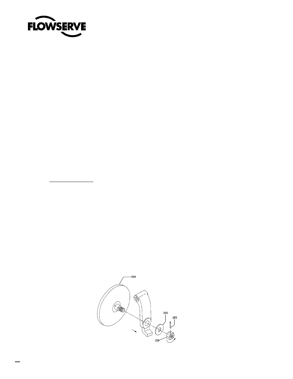
6.1.1.1 Disc/Hinge Connection (Fig. 16)
The disc (004) is attached to the hinge (006) by inserting the pin on the back of the disc
through the hole in the lower end of the hinge. The disc washer (250 or 4A) and the disc nut
(239 or 4B) are then threaded on the pin. With the disc nut tight on the pin, there should be
freedom of movement between the disc and the hinge. If the disc if tightly connected, back off
the disc nut one turn.
If the valve is being reassembled with the original parts, the correct position of the nut can be
determined by aligning the disc nut pin holes in the nut and the disc pin. If new parts are
being used, the hole for the disc nut pin must be drilled through the nut and disc pin. Once
the nut is positioned properly, the disc nut pin (265) should then be inserted into the hole and
the ends peened over.
FIGURE 16