1 subassembly instructions, 1 lb subassembly, qxm and mx units – Flowserve Limitorque QXM Linear Base User Manual
Page 3
3
MXa/QXM Linear Base FCD LMENIM2315-00 – 6/14
flowserve.com
1 Subassembly Instructions
1.1 LB Subassembly, QXM and MX Units
1.1.1 Optional LB Subassembly Removal From QXM and MX Units
Step 1
c
WARNING: Hazardous voltage! Turn off all power sources to actuator before removing actuator from LB assembly.
Power sources may include main power or control power. If necessary, disconnect incoming power leads L1, L2,
L3 and control wiring from terminal block.
Step 2
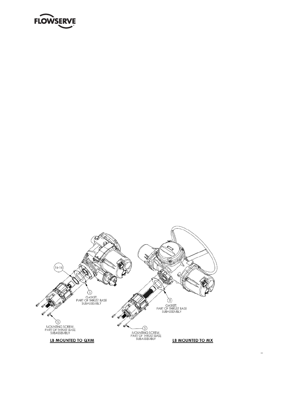
Remove the four bolts (#5) that secure the LB assembly to the actuator base plate and slide down the LB subassembly
until the LB shaft clears the unit actuator.
Step 3
Remove gasket (#5) and slide gasket off thrust base assembly or remove from actuator baseplate.
Step 4 (QXM actuators only)
Remove pilot spacer (#16-16) by sliding over LB shaft.
NOTE: Pilot spacer (#16-16) is used to pilot an ISO thrust base assembly to the QXM adapter plate. If an MSS thrust
base assembly is used on a QXM actuator, the pilot spacer is not required. The MX units do not require this pilot spacer
in this location on any assemblies as long as the MX base plate and thrust base are of the same type, i.e., ISO/ISO or
MSS/MSS.
Figure 1.1 – LB Subassembly Removal From Actuator
NOTE: The thrust base assembly is considered part of the LB subassembly. For this procedure the thrust base parts
are called out as item number (#5) in the figures. Other item numbers may be used in other manuals. For disassembly
and reassembly of the thrust base assembly (#5), refer to the QXM or MX manuals, (QXM) LMENIM3314 section 3
and (MX) LMENIM2306 section 3.