Flowserve Limitorque QXM Linear Base User Manual
Page 5
5
MXa/QXM Linear Base FCD LMENIM2315-00 – 6/14
flowserve.com
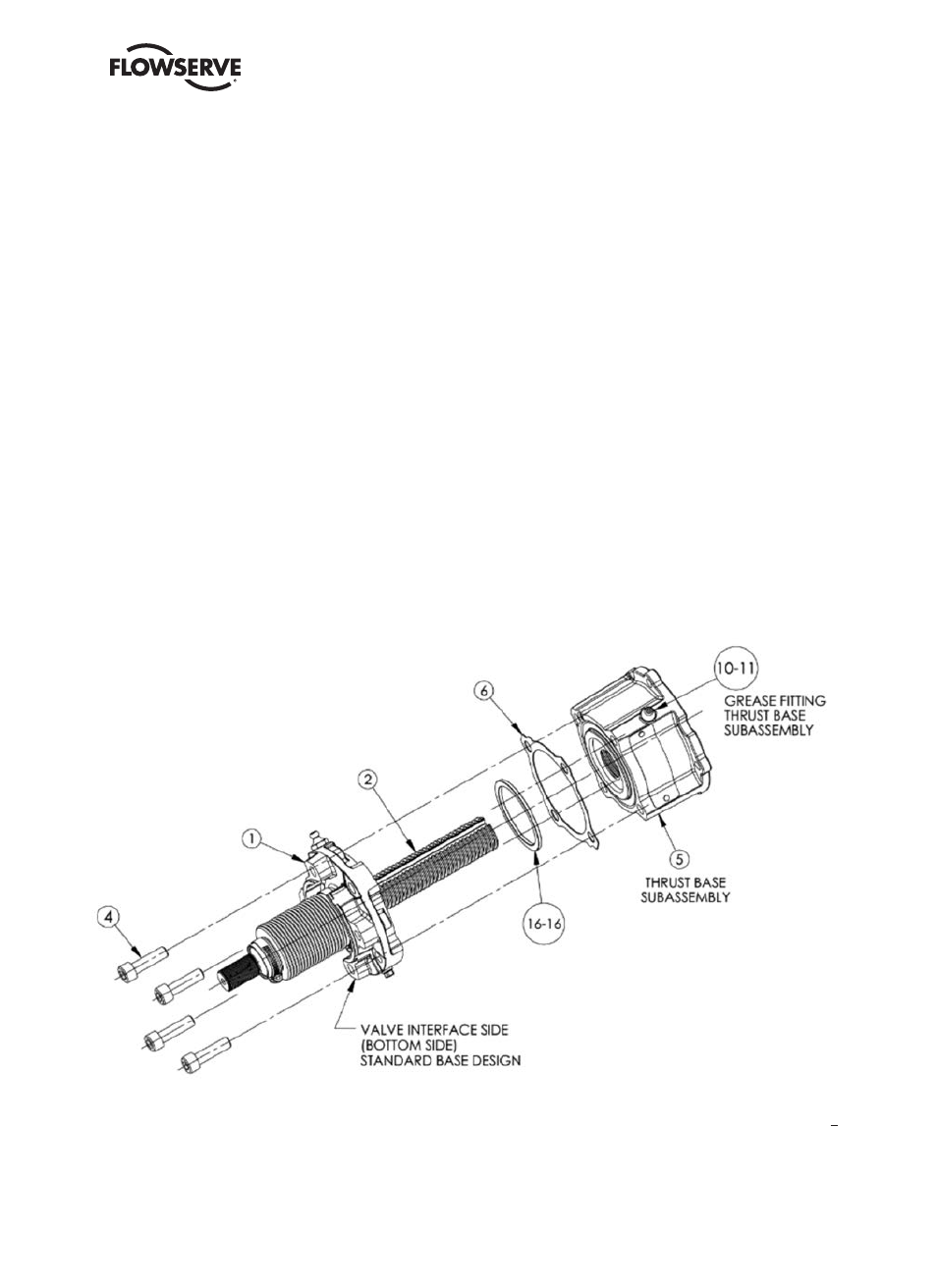
1.1.3 Removal of Thrust Base Subassembly From LB Assembly
Step 1
Remove the four bolts (#4) that secure the thrust base subassembly (#5) to the LB anti-rotation base (#1).
Step 2
Remove thrust base subassembly (#5) by rotating the thrust base up and around the LB shaft threads (#2) until the
thrust base is disengaged from the LB shaft.
NOTE: If the thrust base is still attached to the actuator, the LB assembly may be removed from the thrust base by
rotating the LB assembly down until the LB shaft is disengaged from the thrust base subassembly.
Step 3
Remove gasket (#6), and slide off LB assembly or remove from thrust base.
Step 4
If supplied, remove pilot spacer (#16-16) by sliding over LB shaft.
NOTE: Pilot spacer (#16-16) is used to pilot an MSS thrust base assembly (#5) to the LB anti-rotation base (#1). If an
ISO thrust base assembly is used, the pilot spacer is not required in this location.
This note applies to all LB assemblies mounted to both QXM and MX actuators.
Figure 1.3 – Thrust Base With LB Assembly
LB1 assembly shown in this figure.