Flowserve TX2 Triple Offset High Performance Butterfly Valve IOM User Manual
Page 7
Flow Control Division
7
SECTION VIII
FLANGE CONNECTING & BOLTING
8.1. Keep valve protection boards until installation.
8.2. Make sure the material and size of gaskets could be suitable for the service. Ensure that the faces of flange and
valve are smooth and flat. Sandpaper the faces if there are any defects.
8.3. Check that all the bolts and nuts are in good condition.
8.4. Apply lubricant such as Molybdenum to all the bolts and nuts before fixing them.
8.5. The pipe support(s) may now be required to be partially disengaged. A determination as to pipe flange
alignment and space between the pipe flange and the valve face must be made at this time. The optimum spacing
would be such as to only allow the flange gasket to be installed, at the maximum, and the flange bolt holes would be
concentric.
8.6. The opposite connecting pipe flange face may not be more than 1/4 inch away from the valve flange face.
Alternate methods of alignment, other than using the flange bolts, must be utilized to conform with this requirement.
8.7. Install all studs, maintaining uniform clearance between the studs and the mating bolt holes. Additionally the
studs spanning the valve assembly should not contact the valve body.
8.8. Seat the flange by alternate tightening of four equally-spaced flange bolts no more than 1/4 turn per bolt, until
the flange faces seat. During this operation, it is advisable to continually check the relative distance between the
flange faces. Torque the bolts to approximately 25% of the final torque value (see table 1).
8.9. Inspect the remaining bolts and assure correct alignment. Tighten to the same level as the first four bolts.
8.10. Complete the tightening of all flange bolting in a minimum of four increments to the final determined torque
value.
8.11. Test cycle the valve to be sure that there is no interference or binding.
12. Maximum Torque of Flange Bolt
Bolt size
Torque
(ft-lb)
(Nm)
5/8” (M16)
110
150
3/4” (M20)
200
270
7/8” (M22)
320
434
1” (M26)
480
650
1-1/8”(M28)
600
815
1-1/4”(M32)
840
1140
Table 1.
※Actual torque shall depend on gasket
type, consult gasket manufacturer.
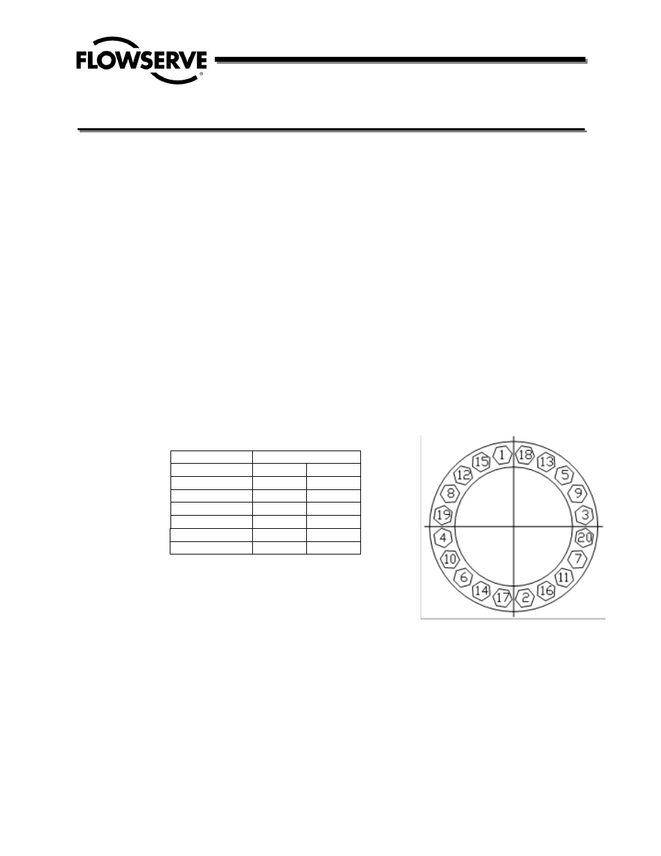
BOLT TIGHTENING SEQUENCE (Fig.9)