Flowserve NAF-Check User Manual
Page 4
Fi 30.79(2)A
NAF-Check takaiskuventtiili PN 25 - PN 100
FI
Asennus - ja hoito-ohjeet läppätakaiskuventtiileille esitteiden
Fk 30.70 ja 30.71 mukaan.
NAF-Check backventiler PN 25 - PN 100
SE
Monterings- och skötselanvisningar för spjällbacksventiler
enligt katalogbladen Fk 30.70 och 30.71.
Clapet de retenue a papillon NAF-Check PN 25 - PN 1
00
00
00
00
00
Instructions de montage pour les clapets de retenue à papillon
FR
conformes aux feuillets de catalogue FK 30.70 et 30.71.
NAF-Check rückschlagventile PN 25 - PN 100
DE
Montage- und Wartungsanweisungen Für Rückschlagklappen
gemäss Katalogblättern Fk 30.70 und 30.71.
Check valves NAF-Check PN 25 - PN 100
GB
Installation and maintenance instructions for tilting disc
check valves as per catalogue sheets Fk 30.70 and 30.71.
Check valves NAF-Check PN 25 - PN 100
GB
Make certain that the disc´s stub shafts are
prefectly horizontal in horizontal lines
..... The
valve is correctly positioned when the lifting eye on
top of the valve body is vertical.
Valves installed in vertical lines must, of course,
also be accuately centered. In all conventional
applications, the valve must open upwards.
PN 40/100 (ASA 300/600) valve´s sealing surfaces
are dimensioned for standard gaskets with a solid
metal external guide
ring according to the standards
listen on the calalogue sheet.
Installation and maintenance instructions for tilting
disc check valves as per catalogue sheets Fk 30.70
and 30.71.
General
The tilting disc check valve NAF-Check is designed
for installation between two pipe flanges in horizon-
tal pipe lines or in vertical pipe lines with upward
flow.
Furter details concerning the design, materials and
dimensions of NAF-Check are given on the rele-
vant catalogue sheet.
Application areas
NAF-Check can be mounted in most installations
requiring a non-return valve function.
Catalogue sheets Fk 30.70 and 30.71 describes
sample applications and gives guidelines for
selecting valves.
Note
that a few types of installations require spe-
cial measures to ensure efficient non-return service.
These are:
•
Low, pulsating gas flows such as are emitted
from a piston compressor.
•
Low-pressure gases-vacuum.
•
Location on suction side of centrifugal pumps.
The valve should be installed on the delivery
side.
•••••
Pumps in parallel.
Measures to solve these problems are described
on the relevant catalogue sheets.
Installation
To obtain optimum function of the NAF-Check and
of the circuit in which it is installed, the following
instructions should be carefully followed. Consult
NAF if in doubt as to the location or function of NAF-
Check.
Clamb the valve between two pipe flanges using
through-bolts. NAF-Check is available for all com-
mon international flange standards; see catalogue
sheet.
A flow-direction arrow
is cast into the valve body-
lifting eye. Make certain that the medium´s flow
coincides with this arrow.
Center the valve carefully between the pipe
flanges so that the disc can move freely
(Fig.
1 and 2) and is not obstructed by the edge of the
pipe flange during operation. (Fig.3).
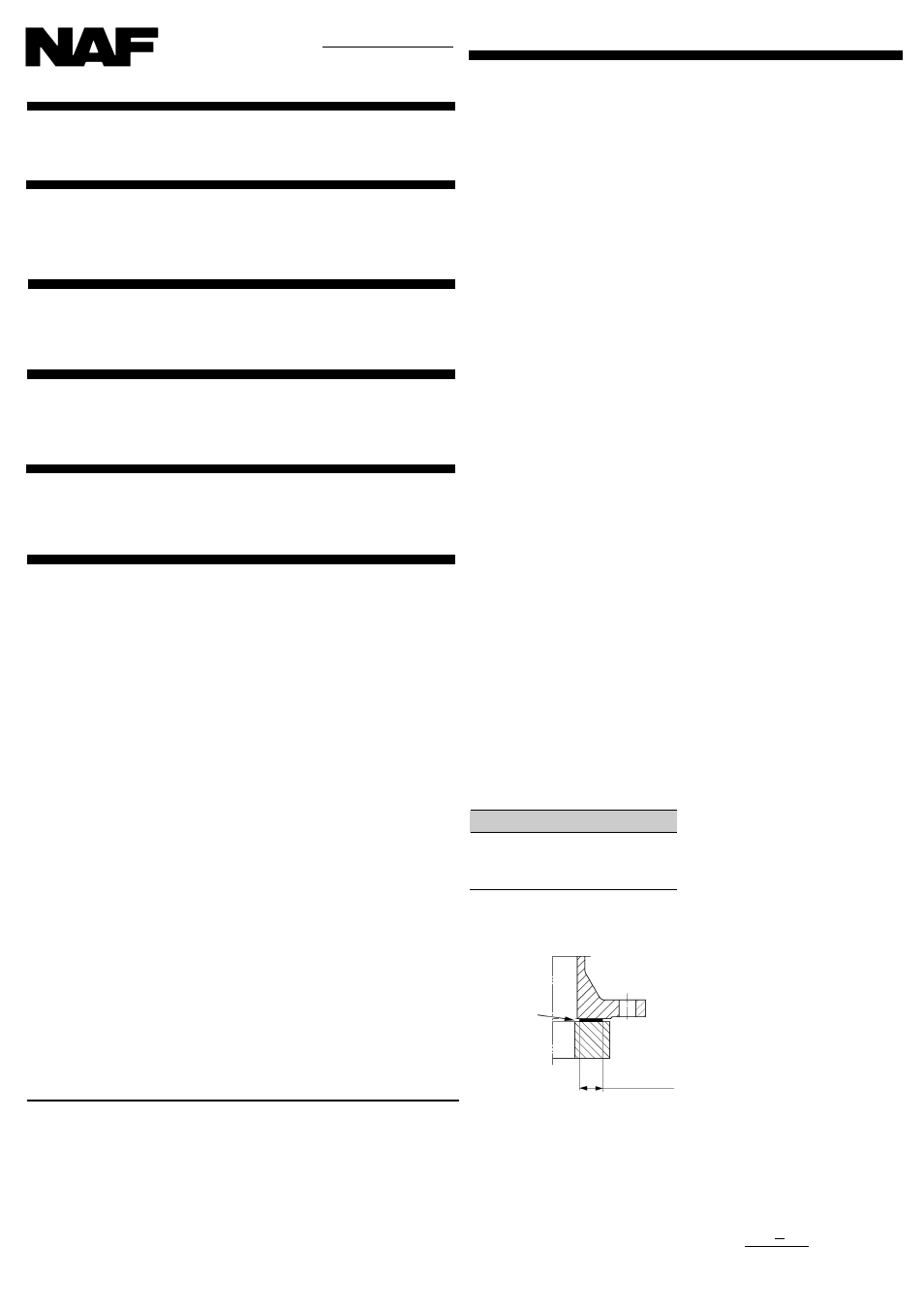
Flange gaskets
NAF-Check has plane gasket faces. We
recommend the following gasket widths for pressure
class NP 25 (ASA 150).
Centering
Insert the two bottom through-bolts in the pipe
flanges an cradle the valve on these two bolts. Use
correctly dimensioned shims to center the valve (Fig.
2). The centering operation may be aided by easing
the valve into place with help of wedges hammered
between the valve body and the through-bolts.
The valve is correctly centered when the distances
at A shown in Fig. 2 are the same at all three
measuring points.
Pipe flange
NAF-Check
Gasket width
Fig. 4
Recommended
gasket widths
The gasket's in-
ner diameter
shall never be
smaller than the
pipe flanges nor
the inner diame-
ter of NAF-
Check.
Both sides of
each gasket shall
fit snugly against
the entire sealing
surface.
DN
Gasket width mm
40 - 150
10
200 - 300
15
350 - 500
18
600 - 1200
25
Maintenance
NAF-Check will normally not require any service
work. The valve is available with an auxiliary spring
to accelerate closing, or without a spring assembly.
The springed version is recommended for fluid me-
dia. A springless versions may easily be equipped
with a spring to obtain extra rapid closing.
Installation of spring assembly
A spring assembly consists of a torsion spring,
a pressure spring, a spacing collar and two locking
pins. (Fig. 6).
DN 65 - 300
Slide the spacing collar in the torsion spring and
thereafter insert the pressure spring and locking
pins in the spacing collar. Mount the spring
assembly on the back side of the disc as follows:
Insert one locking pin in its receiver hole in the disc.
Compress the spring assembly and guide the other
locking pin into its receiver hole. (Fig. 5). The tor-
sion spring will grasp the stop block, slightly pre-
loaded.
DN 350 and bigger:
Locate the torsion spring (E
in Fig. 6) at an angle against one of the holes for the
locking pins in the valve body. Make sure that the
yoke on the torsion spring is able to pass freely un-
der the stop lug (D). Slide the spacing collar (B) into
the torsion spring and then fit one of the locking pins
A, the pressure spring (C) and the other locking pin
in the spacing collar. Press the spring assembly
down so that it takes up the correct position and
take great pains to ensure that the locking pins snap
into their holes. Next, centre the torsion spring on
the spacing collar and make sure that the yoke, with
slight pre-tension, grasps the stop lug in the valve
body.
Spring assembly replacement
DN 65 - 300
Insert a screwdriver between the disc and one end
of the torsion spring (at the inner side of the locking
pin). Press the locking pin into the spacing collar
and use a second screwdriver between the torsion
spring and disc to ease away the spring assembly.
Install a new spring assembly as described above.
DN 350 and bigger
::::: Insert a screwdriver between
one end of the torsion spring, beyond the stop on
the locking pin, and the disc. Press the locking pin
into the spacing collar. Do the same thing on the
other side, using a second screwdriver. Prize up the
spring assembly on one side and remove the locking
pin, pressure spring and spacing collar. Withdraw
the torsion spring slopingly upwards under the stop
lug.
Fit a new spring assembly as described above.
Minimum opening pressure
different
ial
ial
ial
ial
ial
NAF-Check will be opened by a very low pressure
differential, - approx. 0.05 - 0.15 mwg.
However after the system has beem operating for a
period of time, a greater pressure differential may
be required to open the valve; this is due to normal
coating on the seat surface.
For this reason, we recommend that available
opening pressure always is at least 0.5 mwg.
Pressure drop is discussed on the relevant catalogue
sheet.
Capacity
NAF-Check has very high capacity. (See catalogue
sheet). Flow resistance number Z is 3.6* for a fully
open valve.
The capacity of valves in
horizonta
l
l
l
l
l lines may be
increased for extreme requirements by shortening
the stop block. For further informations please
contact NAF. The closing distance and, in turn, the
closing time will thereby be somewhat greater.
* kv (m
3
/h) =
0.006 • 0.66 • a
2
a = valve size mm
√
z
2.98
Replaces Fi 30.79A 9.96
We reserve the right to design
modifications without prior notice
NAF AB
SE-581 87 Linköping
Sweden
Telephone +46 13 31 61 00
Facsimile +46 13 13 60 54
Telex 50069 nafexp s
An Invensys company
Ask for our address list Fk 01.10GB
of representatives in other countries
ISO 9001 Certified