Worcester controls – Flowserve 51 Series Fire-Safe Valves User Manual
Page 7
19406-H
7
Flow Control Division
Worcester Controls
CAUTION: The actuator is a “spring return” model. First
remove two end cap screws diagonally opposite each other,
then lubricate the threads and under the head. Replace the
screws and repeat the procedure for the other two screws. Do
this for each end cap as this will aid reassembly. Now
uniformly loosen all four end cap screws on each end cap two
to three turns at a time, in sequence, to relieve pre-load of the
springs. End cap screws are long enough to allow springs to
relieve before disengaging. Note position of springs, gently pry
off each end cap and use caution when removing end caps.
f. The two-piston guide rod assemblies (4) can now be
removed from each end of the body and disassembled by
removing the piston set screws (12). Do not interchange
piston guide rods and their respective piston. For sizes
10-20 Rev. R6, each guide rod and piston may be press
fitted together (do not use set screws) and cannot be
disassembled. (To assist reassembly, mark the body with
a line on the side from which the guide rod using the thru
hole is removed.) Remove all O-rings (15B and 15C) and
bearings (6B) from pistons.
g. The shaft on Rev. R2 and sizes 10-20 Rev. R3 thru R6
models can only be removed after the piston assemblies
are taken out. Remove the position indicator (17) (if any),
the shaft clip (15F) (not reusable part!) (see note below)
and the S.S. washer from the top of shaft. Then remove
the shaft thru the larger opening in the bottom of the
body. The top bearing (15G) and the O-ring (15D) can
now be removed. Remove the two S.S. washers and
thrust bearing (10) from the top of the shaft and the O-
ring (15E) and bearing (15H) from the bottom end.
NOTE: Some actuators may be using a spiral ring type shaft clip as
shown at right.
To remove this clip, engage the lower end of the ring with a flat blade
screwdriver. Using another flat blade screwdriver push the top end of
the clip in the opposite direction. As the clip I.D. expands lift the clip
from the shaft. the installation of a new clip would be the above steps
in reverse and ensuringthat the edges of the clip are properly seated
in the shaft groove.
The Rev. R1 model, all sizes, and the Rev. R3 thru R6 models, sizes
25 through 35, have an anti-ejection ring (15J), which is a one-piece
spiral wound ring. This ring does not have to be removed and may or
may not be included in repair kits.
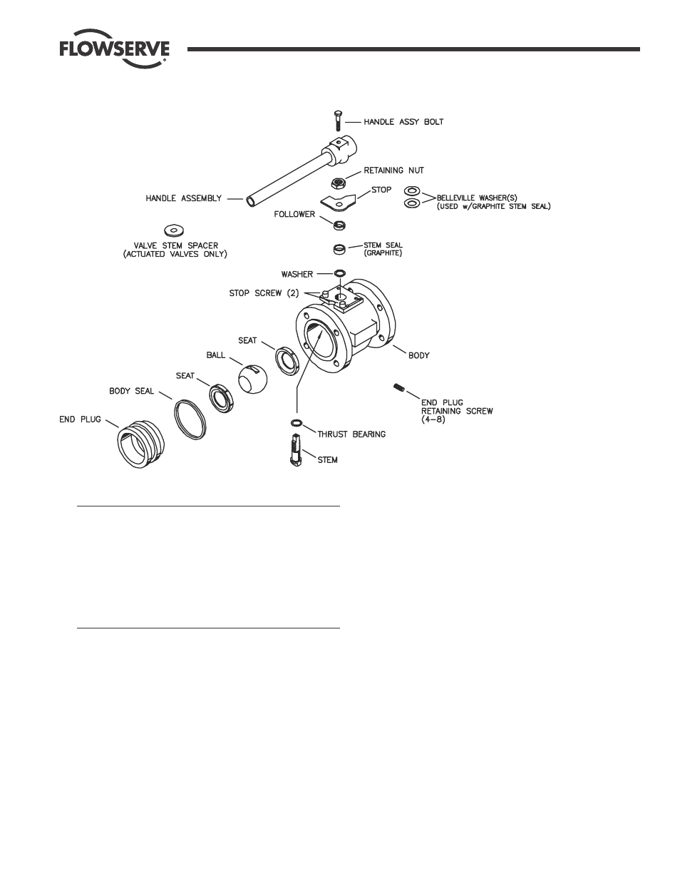
3" and 4" 150# and 300# Flanged Valves