Disassembly procedures – Flowserve Edward Cast Steel Bolted Bonnet Valves User Manual
Page 12
12
Flow Control Division
Edward Valves
Disassembly Procedures
(cont.)
3. Lift the handwheel off the valve, using a
suitable capacity chain hoist for large
handwheels. If the stem of the valve is
mounted vertically, position the hoist
directly above the handwheel,
Otherwise, the hoist should be posi-
tioned slightly away from the handwheel
in line with the stem.
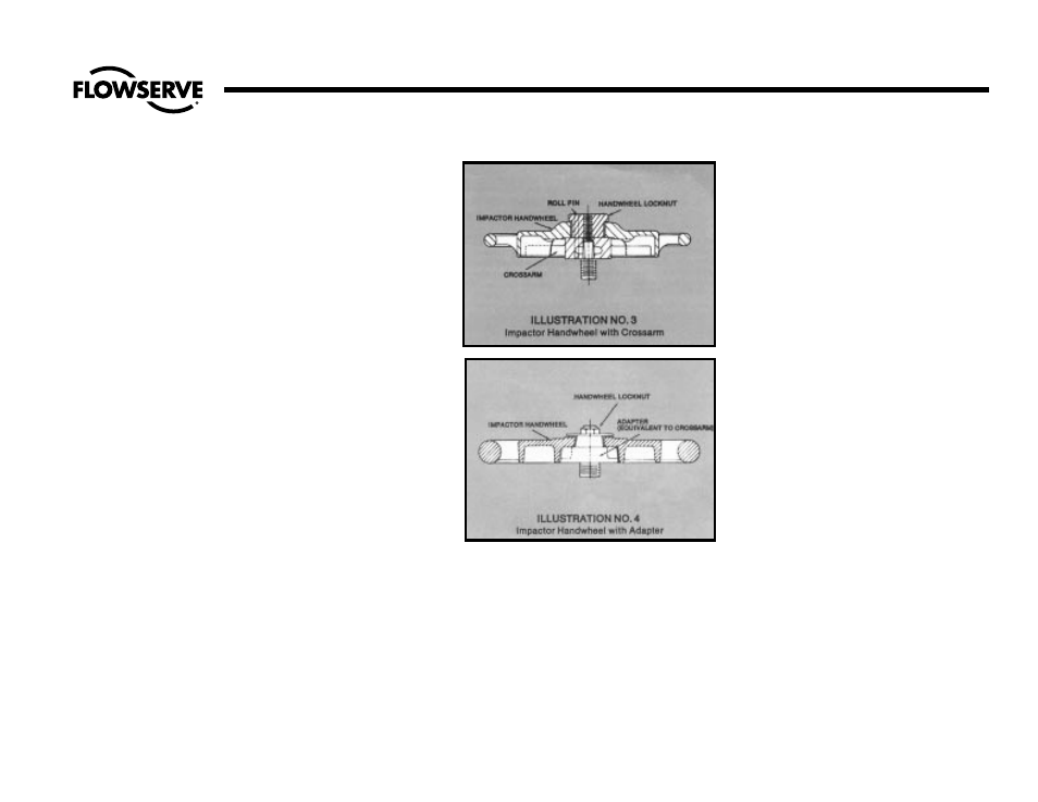
4. Crossarm Removal: For all valves, the
crossarm can be removed by tapping
lightly with a hammer on the underside
and lifting off.
PROCEDURES FOR REMOVING
ELECTRIC ACTUATORS FROM
VALVE BONNETS
Edward bolted bonnet valves use various
types of electric actuators, depending upon
the size and pressure class, which deter-
mine the torque requirements, whether the
stem is revolving or non-revolving and
whether the valve takes the stem thrust
(torque only unit) or the actuator takes the
stem thrust (torque and thrust unit). The pro-
cedures below describe the removal of
these various types from the valve bonnet.
Also included are complete instructions for
resetting the limit switches.
Disassembly procedures for the electric
actuators themselves are not included and
appropriate instructions should be
obtained before starting. Consult the actua-
tor manufacturer.
The actuator can be removed while the
valve is pressurized but caution must be
observed to make certain that the valve is
first in the backseated or fully open position
before removing units from valves with non-
revolving stems. See “Caution, “pg. 11.
All of the following disassembly procedures
are arranged in accordance with the gen-
eral comments of pg. 11. Study these
pages carefully before beginning.
Determine first whether the valve stem is
revolving or non-revolving.
REVOLVING STEM VALVES
On revolving stem valves the actuator drive
nut is connected to the stem through a key.
See Illustration No. 5, pg. 13.
1. Disconnect the electrical wiring to the
actuator.
2. Position a sling on the motor actuator
and attach a chain hoist of suitable
capacity to the sling.
3. Remove the nuts or cap screws from the
underside of the actuator flange.
4. Lift the actuator up and completely off
the stem and stem key.
5. Position the actuator away to a clean
area for further disassembly, if required.
NON-REVOLVING STEM VALVES
On non-revolving stem valves, the actuator
drive nut is threaded to the stem. See
Illustration No. 6, pg. 13.
1. Disconnect the electrical wiring to the
actuator.
2. Make certain the packing gland nuts
are tight.
3. Position a chain hoist of suitable capaci-
ty so the actuator is supported in such a
manner that the handwheel can still be
rotated. If the valve is installed with its
stem other than vertical, the hoist should
be positioned slightly away from the
handwheel in line with the stem.
4. Remove the nuts of cap screws from the
underside of the actuator flange.