Repair procedures – Flowserve Edward Cast Steel Bolted Bonnet Valves User Manual
Page 9
9
Flow Control Division
Edward Valves
5. The final weld should receive any
needed nondestructive testing. This
should include a visual examination and
liquid penetrant or magnetic particle
examination. Some major weld repairs
could even mandate radiography to
ensure a sound weld.
VALVE COMPONENT REPAIR—
DISK-PISTON ASSEMBLY REPAIRS
It is possible that the bearing surfaces on
the O.D. of the disk-piston assembly and
I.D. of the body can become scored
deeply enough to cause a binding or
wedging of the piston assembly in a full,
or partially open or closed position. Such
scores and resulting burrs may be caused
by particles of weld spatter, flakes of hard
line scale or other foreign matter which
has inadvertently gotten into the line. Upon
disassembly burrs must be removed with
emery cloth, and the bearing surfaces
otherwise made smooth and clean again.
Where the burrs on the piston are very
large, it may be more convenient to chuck
the assembly in an engine lathe and file
them off.
GASKET SEAL AREA REPAIR
Where foreign matter of any sort is re-
sponsible for a gasket seal leak on the
sealing surface of the bonnet, it is very
likely that it has caused an impression in
the same sealing surface which must be
removed completely before reassembling.
This can be done by taking a shaving or
skin cut on the sealing surface. In so
doing, it is mandatory that the work be
chucked and square to all existing
diameters and surfaces.
Repair Procedures
(cont.)
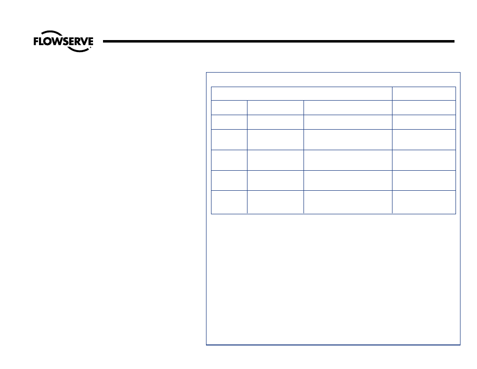
TABLE B – WELDING ROD RECOMMENDATIONS
MATERIAL TO BE WELDED
WELD ROD
RECOMMENDATIONS
ASME IX
Material
ASTM Grade
AWS Classification
P-Numbers
P-1
Carbon Steel
1. ASTM A216, Grade WCB
AWS 5.1
2. ASTM A105
E7018
P-4
1-1/4% Chromium,
1. ASTM A217, Grade WC6
AWS 5.5
1/2% Molybdenum
2. ASTM A182, Grade F11
E8018-B2
Low Alloy Steel
P-5
2-1/4 Chromium,
1. ASTM A217, Grade WC9
AWS 5.5
1% Molybdenum
2. ASTM A182, Grade F22
E9018-B3
Low-Alloy Steel
P-8
18% Chromium,
1. ASTM A351, Grade CF8M
AWS 5.4
8% Nickel
2. ASTM A182, Grade F316
E316
Stainless Steel
P-8
18% Chromium,
1. ASTM A351, Grade CF8C
AWS 5.4
8% Nickel
2. ASTM A182, Grade F347
E347
Stainless Steel
WELDING EDWARD VALVES IN-LINE
When welding a valve in line, the installer
should apply the specific technical rules
imposed by the jurisdictional authority of the
area where the valve is installed, In the
absence of such rules, following are
suggested practices for welding Edward
valves in line:
1. Welding should be done using procedures
and personnel qualified in accordance with
ASME Section IX. Rules for preheat and
postheat are stated in Chapter V of ASME
B31.1 (Power Piping).
2. The valve should be welded in line, one
end at a time, in a closed position (approx-
imately a half-turn after the seat in the body
comes in contact with the disk). This is
suggested to preclude warpage between
seating surfaces caused by temperature
induced stresses during welding or
subsequent heat treat. It also protects the
seat from weld spatter that might coat the
lapped seat and disk. When postweld heat
treat is required, each weld end should be
heat treated one at a time, to minimize
impact of heat on valve internals. Do not
heat treat an Edward valve with a piping
attached as a unit in a furnace, as
warpage of parts may occur. After weld-
ing, open the valve and flush the line to
clean out all foreign matter.