Disassembly procedures – Flowserve Edward Cast Steel Bolted Bonnet Valves User Manual
Page 14
DISASSEMBLY PROCEDURES FOR
VALVE PARTS AREA 2
(For a definition of Area 2, see pg. 11.)
(See Illustration No. 1, pg. 5, for an expla-
nation of valve parts nomenclature.)
Step-by-step disassembly procedures are
described below. The procedures include
disassembly instructions for stop, stop-
check (non-return), and piston lift check
valves. The applicable instructions should
be read thoroughly before the start of dis-
assembly.
All of the following bonnet disassembly
procedures are arranged in accordance
with the general comments on pg. 11.
Study these pages carefully before
beginning.
STOP AND STOP-CHECK
(NON-RETURN) VALVES
See Illustration No. 1, pg. 5.
1. Loosen the packing gland bolt nuts and
tap the gland which should relieve any
pressure which might be trapped in the
valve. This is important.
2. Carefully remove the bonnet stud nuts or
cap screws.
3. Remove the packing gland bolts nuts.
4. Use a chain hoist in line with the stem to
lift the stem-bonnet assembly out of the
body. During this process, mark the
body bonnet, and gasket at correspond-
ing points (other than sealing surfaces)
so that their relative position can be
duplicated in reassembly. In laying the
parts aside for inspection, it is impera-
tive that they be placed carefully on a
bed of rags or other soft material to
avoid marring any machined surface,
particularly any seating and sealing sur-
faces.
5. Unscrew the stem from the bonnet bush-
ing.
6. On stop valves, the disk and disk-nut
assembly is attached to the stem. On
stop-check (non-return) valves, the piston
disk assembly is not attached to the
stem and must be removed separately.
See Step 7.
7. Screw 3/8 – 16 UNC bolts (1/2 – 13
UNC on 12" valve) into the threaded
bosses or nuts provided in the piston.
The piston now can be lifted from the
valve. Occasionally, a vacuum may be
formed by the cooling fluid in the pipe
line below the valve. Until relieved, this
vacuum will prevent removal of the pis-
ton.
8. The bonnet end opening should be kept
covered whenever possible.
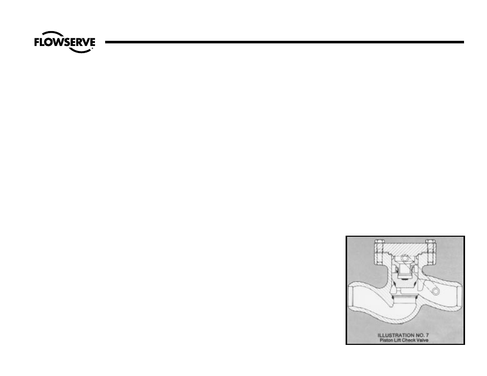
PISTON LIFT CHECK VALVES
See Illustration No. 7.
Piston lift check valves are constructed with
valve bodies similar to the corresponding
stop or stop-check (non-return type valves.
Disassembly is simplified by the absence of
a yoke and stem.
NOTE: Care must be taken in removing the
cover bolting in case pressure should be
trapped in the body (downstream piping).
Check to make certain all downstream
pressure is relieved.
1. Carefully remove the cover nuts or cap
screws observing the above caution.
2. Lift the cover off the valve. During the
process, mark the body, cover and gas-
ket at corresponding points (but not on
the sealing surfaces) for reference and
reassembly. In laying the parts aside for
inspection, it is imperative that they be
placed carefully on a bed of rags or
other soft material to avoid marring any
machined surface, particularly any seat-
ing and sealing surfaces.
3. Screw 3/8 – 16 UNC bolts (1/2 – 3
UNC on 12" valve) into the threaded
bosses or nuts provided in the piston.
the piston now can be lifted from the
valve. Occasionally, a vacuum may be
formed by the cooling fluid in the pipe
line below the valve. Until relieved, this
vacuum will prevent removal of the pis-
ton.
14
Flow Control Division
Edward Valves
Disassembly Procedures
(cont.)