Auxiliary dry contact input, Odometer function, Valve stroke time out function – Flowserve BUSwitch with Foundation Fieldbus Communications Protocol User Manual
Page 10: Additional tb parameters
AX
ENIM0048-01 (Firmware Rev. Nov. 12 99) (AUTO-48) 11/01
Page 10 of 16
©2001, Flowserve Corporation,
Springville, UT
Flowserve Corporation
1350 South Mountain Springs Parkway
Phone: 801
489 2233
Flow
Control
Division Springville,
Utah
84663
Facsimile:
801
489
2228
Automation
Business
Unit www.flowserve.com
Email:
Automax Valve Automation Systems
Product Specification
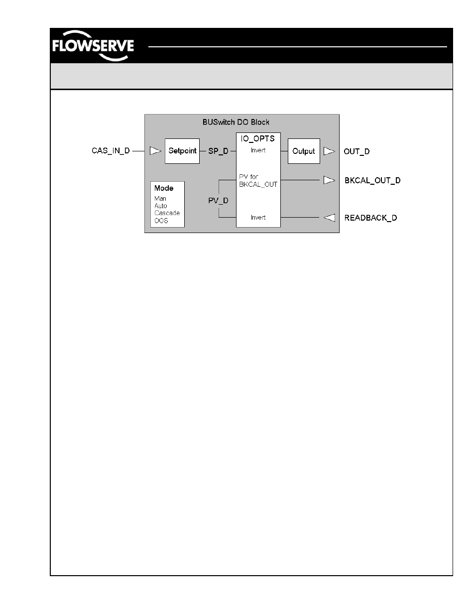
Figure 5 – DO Block Schematic
F
OUNDATION
® Fieldbus DO blocks write the
READBACK_D value to the PV_D variable within each
block. PV_D may then be linked to the BKCAL_OUT
variable. Figure 5 shows a schematic of a DO block
illustrating this feature.
To link DO.PV_D to DO.BKCAL_OUT, configure the
IO_OPTS for the desired block to “PV for BKCAL_OUT.”
Note: This action prevents the use of “Invert” as an IO
Option. Then, link BKCAL_OUT to the BKCAL_IN of the
function block sending the CAS_IN_D signal.
Option 2. The OUT_D parameter of DI-3 reports status of
the closed limit switch. The OUT_D parameter of DI-4
reports status of the open limit switch. These values are
linkable for interconnectability of field function blocks to
establish more sophisticated process control strategies.
Option 3. The Single Readback option can be activated
by the OPERATION parameter in the Transducer Block.
This option provides a digital feedback of limit switch
status on the DO-1 function block at the READBACK_D
parameter. The digital feedback reports the following
values: 0 = both switches untripped, 1 = closed switch
tripped, 2 = open switch tripped, 3 = both switches tripped.
This option permits a single tag to be allocated per device,
a particularly advantageous feature for DCS applications
where licensing fees are based on the total number of
device tags.
Auxiliary Dry Contact Input
The BUSwitch™ TB also monitors continuity across
terminals P4. This status is seen in the external alarm
parameter and in the OUT_D of DI-2. DI-2.OUT_D will
read Discrete 1 when no continuity exists and the
“Normally Closed” J1 and J2 jumpers are selected. When
contact is made in this jumper mode, the output changes
to Discrete 0.
To reverse the outputs, change the J1 and J2 settings to
“Normally Open.” Refer to Figure 3 for the jumper
settings.
Odometer Function
TB Parameter ODOMETER reports the number of open-
closed and closed-open transitions. It may be reset using
the RESET_ODOMETER parameter. Simply write a
“True” value to this parameter to reset.
Valve Stroke Time Out Function
The BUSwitch™ times each valve stroke and reports the
time from the move command until the appropriate
position switch is tripped. The stroke time is displayed in
the transducer block parameter “TRANSITION TIME.” If
the “TRANSITION TIME” is greater than the value entered
in “TIME-OUT” an alarm is generated. This alarm is
displayed in the transducer block parameter
“TRANSITION-ALARM ” and is also sent to the DI1 block
“OUT-D.” This is a “linkable” input and can be used to
alter process control. The alarm will stay present until the
“RESET-TIMEOUT” parameter is set to “TRUE” in the
transducer block.
Additional TB Parameters
Several TB parameters exist to store information about the
valve, actuator and BUSwitch™ device. In addition,
calibration information may be stored. Refer to the
complete list of BUSwitch™ TB parameters starting on
page 11 for a description of these parameters.