Flowserve BUSwitch with Foundation Fieldbus Communications Protocol User Manual
Page 9
AX
ENIM0048-01 (Firmware Rev. Nov. 12 99) (AUTO-48) 11/01
Page 9 of 16
©2001, Flowserve Corporation,
Springville, UT
Flowserve Corporation
1350 South Mountain Springs Parkway
Phone: 801
489 2233
Flow
Control
Division Springville,
Utah
84663
Facsimile:
801
489
2228
Automation
Business
Unit www.flowserve.com
Email:
Automax Valve Automation Systems
Product Specification
Transducer Block
The Transducer Block (TB) provides the link between
standard function blocks (DO-1, DO-2, DI-1, DI-2, DI-3 &
DI-4) and the sensors and piezo/coil actuators within the
BUSwitch™ device. It tracks number of valve strokes.
The TB also provides some configuration flexibility.
This section details those parameters affecting the
function and configuration of the BUSwitch device. This
discussion includes all operational aspects of the function
blocks as well. A complete list of TB parameters follows at
the end of the section. Complete function block parameter
lists are provided in Appendices A and B.
Pneumatic Actuator Operation – Single Coil,
Fail Open or Fail Closed
For operation requiring a consistent fail position (either
open or closed), select the “Single Coil” TB.OPERATION
parameter. One DO block (DO-1) is used. The TB reads
DO-1 OUT_D Value and energizes both the OPEN (P6)
and CLOSE (P5) terminals as shown in the Single Coil
Truth Table. To reverse the actuator fail mode for double
acting actuators, reverse ports 2 and 4. To reverse
spring-return actuators, actuator modification is necessary.
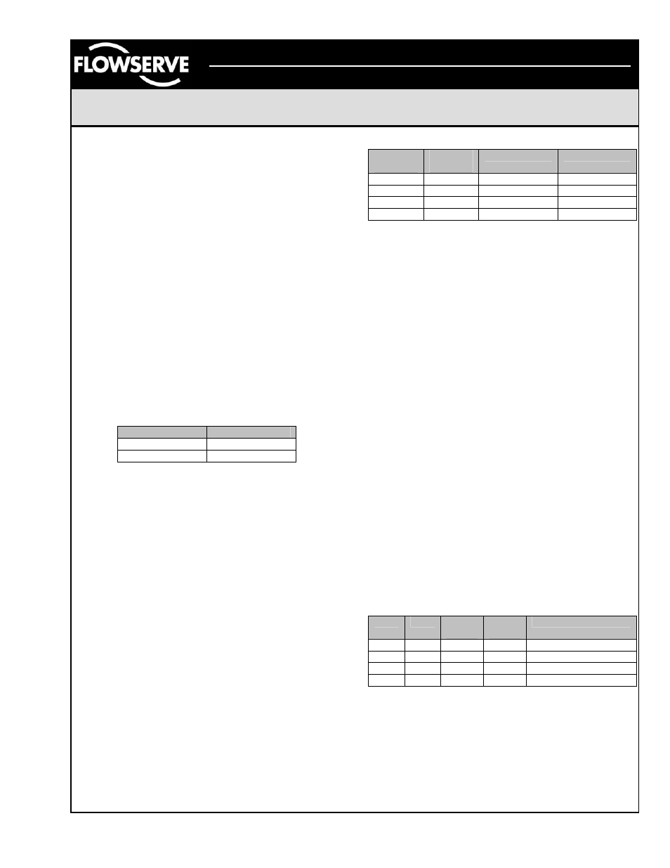
Single Coil Truth Table
DO1.OUT_D
OPEN/CLOSE
0 De-energized
1 Energized
When in Auto mode, DO1.OUT_D follows the SP_D
Value. If the user wishes to invert the above truth table
relative to SP_D, change the function block IO_OPTS
parameter to “Invert.” This will energize the coil on an
SP_D Discrete 0 and de-energize on an SP_D Discrete 1.
This toggle has the same effect when “dual coil” mode is
selected; it is necessary to select “Invert” for both DO
blocks.
Pneumatic Actuator Operation – Dual Coil,
Fail in Last Position
Select the “Dual Coil” TB.OPERATION parameter. Dual
Coil Operation uses both DO1.OUT_D and DO2.OUT_D
block parameters configured in an interlocking manner.
For valve movement to take place, the OUT_D parameters
must take on opposite values as shown in the next table.
Dual Coil Truth Table
DO1
OUT_D
DO2
OUT_D
CLOSE
OPEN
0
0
No Change
No Change
1 0
Energized
De-energized
1
1
No Change
No Change
0 1
De-energized
Energized
Referring to Figure 2, energizing the “OPEN” terminals will
provide air to Port 4 and energizing the “CLOSE” terminals
will provide air to Port 2. To reverse the valve operation,
either reverse the solenoid valve wires on P5 and P6, or
reverse the actuator tubing connections on Port 2 and 4.
The TB.OUTPUT_CONFIGURATION parameter selects
whether piezo/coil pilot elements stay energized or
become de-energized after the valve reaches its desired
position. If the “Pulse” option is selected, the elements will
de-energize after the length of time selected in the
TB.TIME_OUT parameter. The “Constant” setting
maintains element voltage until new DO-1 and DO-2
OUT_D values are selected.
Valve Position Monitoring and Reporting
The BUSwitch™ TB monitors the status of two limit
switches. SW1 is the upper switch and is set to trip when
the valve reaches the closed position. SW2 is the lower
switch and is set to trip when the valve is open. The
TB.CLOSED_SWITCH parameter displays SW1 status as
False when not tripped and True when tripped.
TB.OPEN_SWITCH parameter displays SW2 status the
same way.
The BUSwitch permits three user-selectable options for
reporting limit switch status: 1) Feedback through DO-1
and DO-2, 2) “Linkable” feedback through DI-3 and DI-4,
and 3) Digital feedback through DO-1.
Option 1. The TB provides limit switch status to the
READBACK_D parameters of DO-1 and DO-2
respectively per the following truth table.
Truth Table for READBACK_D Values
SW1
SW2
DO-1
RDBK
DO-2
RDBK
Meaning
A
A
1
1
Improper switch adj.
A
O
1
0
Actuator CLOSED
O A 0 1
Actuator
OPENED
O
O
0
0
Actuator is moving
A = Activated or Tripped, O = Open or Not Tripped