Flowserve MX/QX Profibus DP/PA Field Unit User Manual
Page 53
53
PB DPV1 / PA Field Unit Installation and Maintenance FCD LMENIM2336-03 – 12/12
flowserve.com
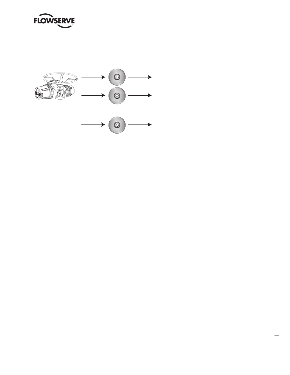
Figure 3.12 – MX/QX PROFIBUS Configuration Requirements
PROFIBUS
Configuration Tool
PROFIBUS
Engineering Tool
GSD File for Description of
Communications Parameters
Electronic Device Description File
for Specification of Functionality
GSD
PROFIBUS
Communication
DTM/FDT Frame
Device Type Manager
EDD
DTM
3.8 GSD and Electronic Device Description,
and DTM Files
PROFIBUS Configuration Tools use device-specific device database files called “GSD” files to
configure PROFIBUS DP and PA devices. This simple text file (ASCII Format) provides information on
cyclic parameters only. Within this file, bus timing parameters, baud rate capabilities, available cyclic
data modules, and slot information specific for the MX/QX actuator device are described.
The configuration tool reads the GSD file and provides the network user with the available process
data or cyclic data parameters. The user can choose to use the default configuration or specify their
own configuration based on process needs. The configuration tool transfers the MX/QX PB configu-
ration and parameter information to the PROFIBUS master. The master transfers the configuration
with parameters to the slave (MX/QX PB) at power up or restart. The slave verifies and confirms the
receipt of the parameters to the master.
Electronic Device Descriptions (EDDs) provide a description of the configuration parameters in
the MX/QX PB to the host engineering tool. The EDDs are written in a standard Electronic Device
Description Language (EDDL) which is readable by hosts that support the standard EDD language.
This engineering tool is then made aware of all of the configuration parameters (acyclic data) in the
MX/QX device. At this point the user can configure the block parameters to meet the needs of the
runtime process.
Function Block definitions and their associated EDD description are organized into a hierarchy of
common parameter sets depending on application area, device function, and manufacturing specific
capabilities.
The Device Type Manager (DTM) provides an interface between its specific application software and
a host’s Field Device Tool (FDT) frame. The DTM can be integrated into FDT frame applications to
allow users to perform offline and online parameterization, configuration, and status and diagnostic
retrieval.