2 connection with valve and mounting kit – Flowserve LPS Pneumatic Heavy-Duty Actuator Series User Manual
Page 12
LPS Series Heavy-Duty Actuators FCD LFENIM0001-02-AQ – 5/15
12
2.2.1
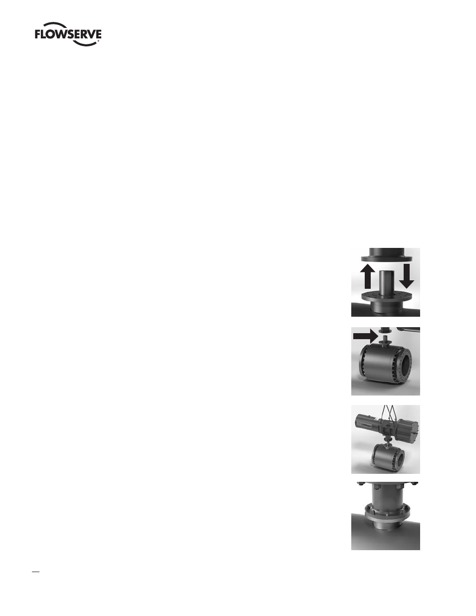
Check the mounting surfaces, the stem adaptor and the spool piece
to assure proper fit. Clean the flanges of the valve and spool piece to
remove oils and greases since the torque is transmitted by friction. Also,
remove any rust that may have occurred during storage.
2.2.2
Secure the valve (possibly with the stem vertical) in the Close position
in case of Single Acting Fail Close actuator and in Open position in
case of Single Acting Fail Open actuator; in case of Double Acting Fail
Last actuator, secure the valve in the same Close/Open position as the
actuator that will be installed onto the valve.
2.2.3
Lift the actuator by the specific lift points (eyebolts), using a proper
lifting system. Position the actuator over the valve and lower to engage
the stem adaptor to the actuator bore. Continue to lower until the spool
piece sits on valve mounting surface. This coupling has to take place
without force and only with the weight of the actuator. The mounting
bolts (or studs) of the valve should easily fit into the bolt holes of the
spool piece without any binding. If needed, turn or stroke the actuator a
few degrees and/or adjust the actuator travel-stops.
2.2.4
The mounting nuts (or bolts) connecting the base of the spool piece to
the valve flange must be evenly tightened according to tightening torque
table without lubricant (Table 2 in Annex section).
NOTE: In some cases, the coupling between valve and actuator can be
direct, without the need of a spool piece. In these cases, Flowserve can
provide an intermediate adaptor flange (fitted under the actuator base)
and a special bushing to be inserted into the yoke bore.
NOTE: The air supply port and discharge are indicated by dedicated plates positioned close to the ports, as shown in Figure
13. In case of a double acting actuator, the ports for the air supply are identified by a number, according to ISO 5599-2.
NOTE: The direction of rotation is identified by a dedicated plate, as shown in Figure 10, in accordance with EN 15714-3.
Before mounting the actuator to the valve, manually open and close valve (if possible), to ensure it is not stuck. Be
sure valve and Limitorque actuator rotate in the same direction and are in the same position (i.e., valve closed, actuator
closed). The assembly position of the actuator, with reference to the valve, has to be in accordance with the plant
requirements (actuator axis parallel or perpendicular to the pipeline axis).
2.2 Connection With Valve and Mounting Kit
The LPS actuator is usually supplied with the spool piece already assembled. To assemble the actuator onto the valve,
perform the following steps: