3 pneumatic cylinder maintenance – Flowserve LPS Pneumatic Heavy-Duty Actuator Series User Manual
Page 22
LPS Series Heavy-Duty Actuators FCD LFENIM0001-02-AQ – 5/15
22
* Standard maintenance spare parts for on/off applications
X Spare parts that can be replaced
• Spare parts that can be replaced without removing the actuator from the valve
Num Description
Qty Spare Parts*
Num Description
Qty Spare Parts*
19
Cylinder Head Flange
1
28
O-Ring
2
X •
20
Piston rod
1
29
O-Ring
2
X •
21
Bushing
2
30
Tube
1
22
Piston
1
31
Tie Rod
12
23
Tape Guide
2
X •
32
Spiral Retaining Shaft
Ring
2
24
Split Ring
2
33
O-Ring
1
X •
25
Stop Bolt Assembly
1
34
Spacer (if necessary)
1
26
Hex Nut (High)
12
27
Cylinder End Flange
1
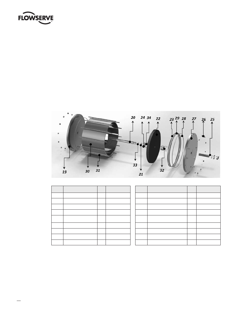
Figure 25: Exploded View of Pneumatic Cylinder
4.3 Pneumatic Cylinder Maintenance
The standard pneumatic cylinder maintenance mainly consists in the replacement of those parts that may degrade over
time, even in the absence of faults. These components are the o-rings and the sliding elements of the piston.
The substitution of cylinder components (or of the whole cylinder) is not expected over the entire actuator life. However,
accidental events may result in damage to these components. In these cases, proceed as described in the following steps.
There are two possible types of maintenance: standard maintenance which can be performed in the field without the
need to remove the pneumatic cylinder from the actuator, and a more thorough maintenance, following unexpected
events, which can be performed only after removing the cylinder from the actuator.
c
DANGER: Do not attempt this maintenance operation with cylinder under pressure.
Standard In-field maintenance
a
WARNING: Before performing any maintenance operation on the cylinder it’s mandatory to remove the pressure
inside the cylinder itself. Make sure that the pneumatic connection ports of the cylinder are disconnected and open
to the ambient. Also make sure that all pneumatic supplies to the control unit and all power supplies are discon-
nected. Make sure that the actuator is in the fail position, i.e., that it is not locked in a position with the spring
compressed by means of the locking tool (as described at paragraph 3.2.2).
a
WARNING: Use the pneumatic cylinder only for the intended function it has been designed for.
NOTE: During the maintenance operation inside the cylinder it’s suggested to have a visual check of the internal
parts of the cylinder in order to guarantee their integrity.