Flowserve LPS Pneumatic Heavy-Duty Actuator Series User Manual
Page 21
21
LPS Series Heavy-Duty Actuators FCD LFENIM0001-02-AQ – 5/15
flowserve.com
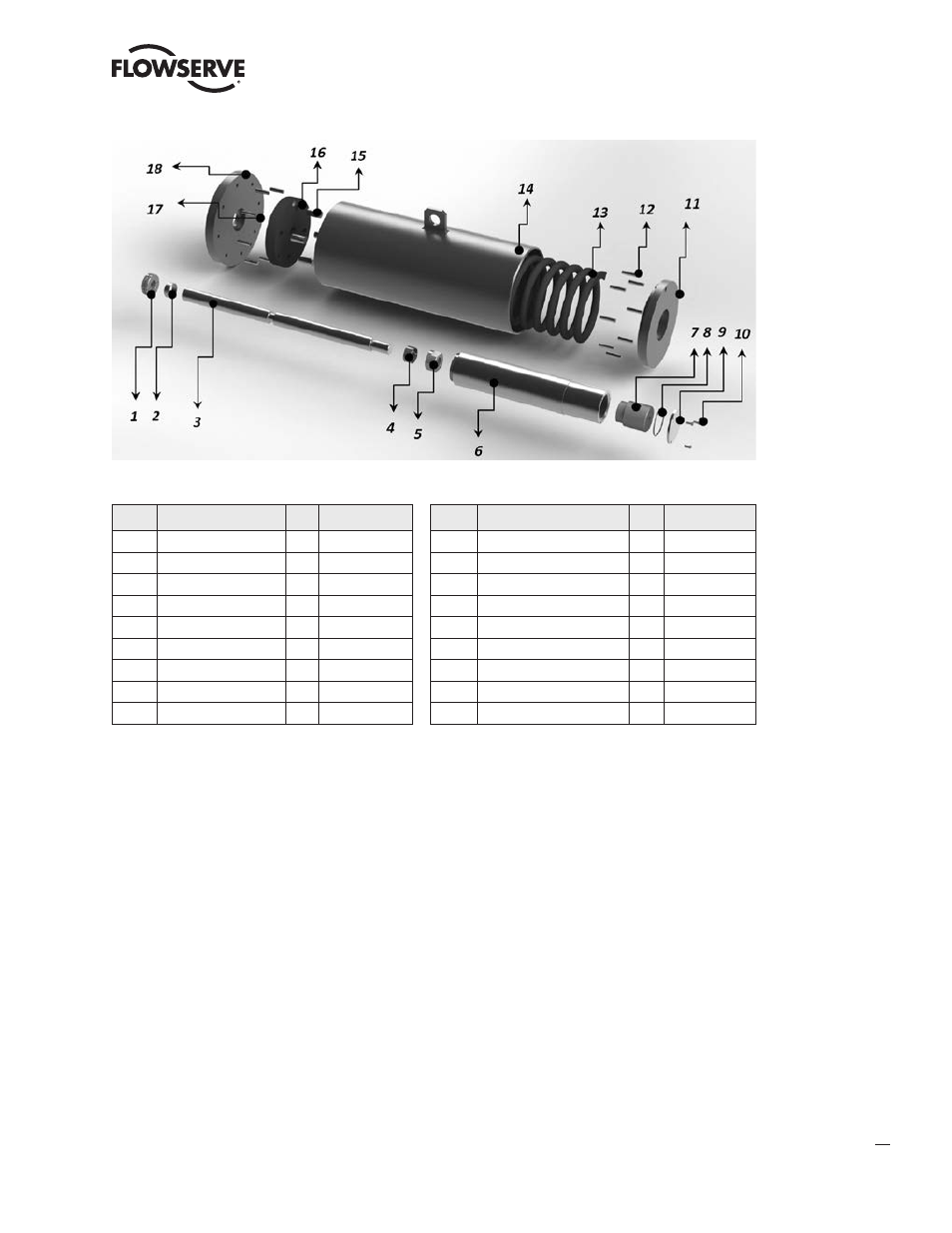
Num Description
Qty Spare Parts*
Num Description
Qty Spare Parts*
1
Split Ring
1
10
Hex Screw
1
2
Bushing
1
11
Spring Can End Flange
1
3
Spring Rod
1
12
Bar Pin
8
4
Bushing
1
13
Spring
1
5
Spring Rod End Nut
1
14
Spring Can
1
6
Spring Guide
1
15
Bar Pin
4
7
Spring Stop Bolt
1
16
Spring Plate
1
8
O-Ring
1
17
Bar Pin
8
9
Stop Bolt Cap
1
18
Spring Can Head Flange
1
* Standard maintenance spare parts for on/off applications
4.2.1
Unscrew and remove the travel-stop of the pneumatic cylinder (25). For removing the stop, refer to
paragraph 2.3. If necessary, feed the pneumatic cylinder from the port on the head flange (27) at minimum
necessary pressure to facilitate the movement of the Scotch yoke and assure the total retraction of the piston
rod (20). Remove the pressure. This way the spring is fully extended.
4.2.2
Remove the cover (46) from the housing by unscrewing all of the locking components: hex screw (45),
hex head shoulder bolts (44) and eyebolts (42) plus upper nuts (43). Leave the studs (41) screwed into the
Scotch yoke housing (51).
4.2.3
Hook and hold in tension the spring container using the specific lifting lug located on the top of the spring
can (shown in the above picture). Care should be taken to choose lifting equipment. Locate the studs (57)
that connect the Scotch yoke housing with the spring container. Carefully un-screw the nuts (56) and the
studs (57). Pull out the whole spring container.
NOTE: Take care to horizontally support the spring module during removal, so as not to damage the spring
rod or the stud threads.
4.2.4
Before reassembling the new spring module to body, make sure stud threads are free of any dirt, shavings,
or other debris. Clean threads with rag and solvent if required, and lubricate threads with an anti-seize
compound. Assemble the new spring can, following the reverse procedure as described in points 4.2.3 to
4.2.5. Readjust the travel stop (25) of the pneumatic cylinder, as instructed in paragraph 2.3.
Figure 24: Spring Can Exploded View