2 actuator connected to the valve – Flowserve LPS Pneumatic Heavy-Duty Actuator Series User Manual
Page 17
17
LPS Series Heavy-Duty Actuators FCD LFENIM0001-02-AQ – 5/15
flowserve.com
3.1.3
Remove the spring can, carefully following the instructions given
in paragraph 4.2. Manually rotate the yoke (36) counterclockwise
(or clockwise, depending on the original fail configuration) up to a
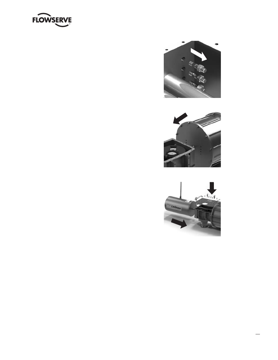
position of approximately 45°. Locate the studs (57) that connect the
housing to the pneumatic cylinder. With the Scotch yoke rotated of
45°, it is possible to easily access these studs. Carefully unscrew the
nuts (56) and the studs (57). Pull out the whole pneumatic cylinder
(the stem is fully retracted).
NOTE: Take care during removal, so as not to damage the piston rod
or the stud threads.
3.1.4
Change the adapter kit. Replace the adapters (54 and 55) designed for
fail close (open) action, with the new ones designed for the opposite
action.
NOTE: Take care to choose the adapter kit suitable for the Scotch yoke
type in use (symmetric or canted).
Reassemble the pneumatic cylinder with adapter, using the reverse
procedure as described in point 4.3.
NOTE: You can identify the cylinder adapter to the spring can adapter
through the three grub screws (53).
3.1.5
Manually rotate the Scotch yoke (36) until the guide block (48) is in
contact with the piston rod adapter (54), in correspondence of the
relevant slot.
Reassemble the spring can, as instructed in paragraph 4.2.
Reposition the cover, taking care to replace the cover gasket (47)
and tighten the screws in according with the torque table 2 and
table 3. Readjust the stops, as instructed in paragraph 2.3.
Periodically operate the actuator to check the functioning in the
new fail configuration.
3.2 Actuator Connected to the Valve
(and the valve can be stroked)
NOTE: If the valve cannot be stroked, due to the requirements of the plant, the actuator must be removed from the valve
and the procedure described in paragraph 3.1 shall be followed. Then the actuator should be reinstalled in the same
position of the valve, following the instructions given in paragraph 2.2.
a
WARNING: Ensure that the pneumatic connection ports of the cylinder are disconnected. Also make sure that all
pneumatic supplies to the control unit and all power supplies are disconnected. Finally, make sure that the actuator
is in fail position, i.e., that it is not locked in a position with the spring compressed by means of locking devices.
3.2.1
Apply the minimum necessary pressure to the cylinder pneumatic port on the end flange and move the
actuator to approximately 45°. If the actuator is provided with a manual override, you can use it to perform
this operation.